Interconnection enclosure having a connector port and preterminated optical connector

a technology of preterminated optical fibers and enclosures, which is applied in the direction of optics, fibre mechanical structures, instruments, etc., can solve the problems of reducing the service life of the enclosure, and reducing the risk of damage to the optical fiber. , to achieve the effect of reducing the risk of damage to the optical fiber and maintaining the bend radius control

Inactive Publication Date: 2005-02-15
CORNING OPTICAL COMM LLC
View PDF15 Cites 308 Cited by
  • Summary
  • Abstract
  • Description
  • Claims
  • Application Information

AI Technical Summary

Benefits of technology

To achieve the foregoing and other objects, and in accordance with the purpose of the present invention as embodied and broadly described herein, the present invention provides various embodiments of optical fiber interconnection enclosures having a connector port and preterminated connectors that may be withdrawn and reloaded from the exterior of the enclosure without entering the interior of the enclosure. In various embodiments, the present invention describes factory and field-installed interco

Problems solved by technology

This costly and time consuming process requires sending a technician to the site, removing a portion of the cable sheath at a predetermined location, locating the appropriate optical fibers, cutting the appropriate optical fibers, branching and/or splicing the optical fibers to a drop cable optical fiber and installing an enclosure.
Too great a tensile force applied to an optical fiber, such as that applied by the weight of a drop cable or environmental factor, may damage the drop cable, splice point, distribution cable and other branched optical fibers.
Conventional enclosure design does not adequately provide for bend radius control and fiber travel limitation.
More im

Method used


Image

  • Interconnection enclosure having a connector port and preterminated optical connector
  • Interconnection enclosure having a connector port and preterminated optical connector
  • Interconnection enclosure having a connector port and preterminated optical connector

Examples


Embodiment Construction

The present invention will now be described more fully hereinafter with reference to the accompanying drawings in which preferred embodiments of the invention are shown. This invention may, however, be embodied in many different forms and should not be construed as limited to the embodiments set forth herein. These exemplary embodiments are provided so that this disclosure will be both thorough and complete, and will fully convey the scope of the invention to those skilled in the art. Like reference numbers refer to like elements throughout the various drawings.

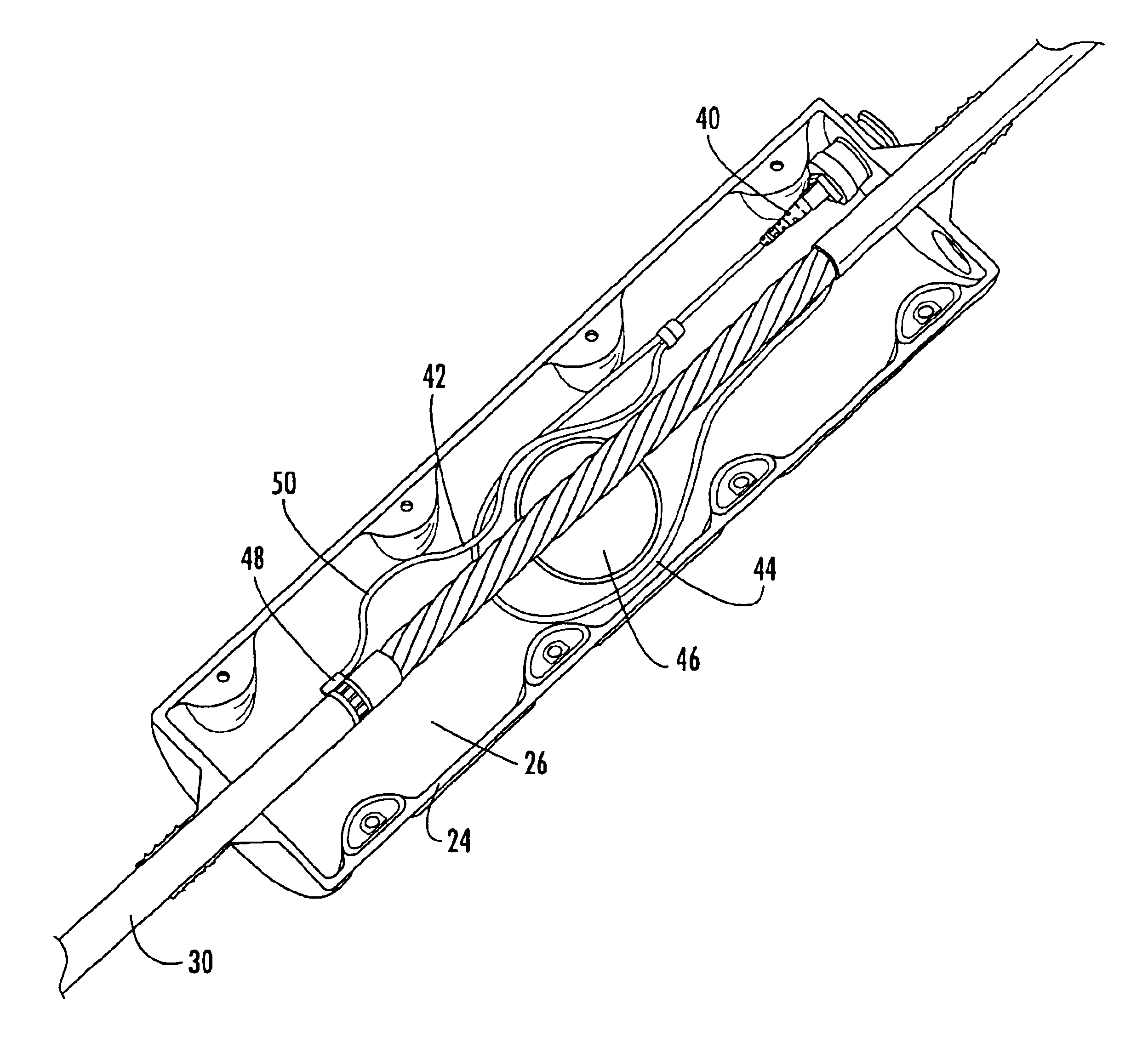
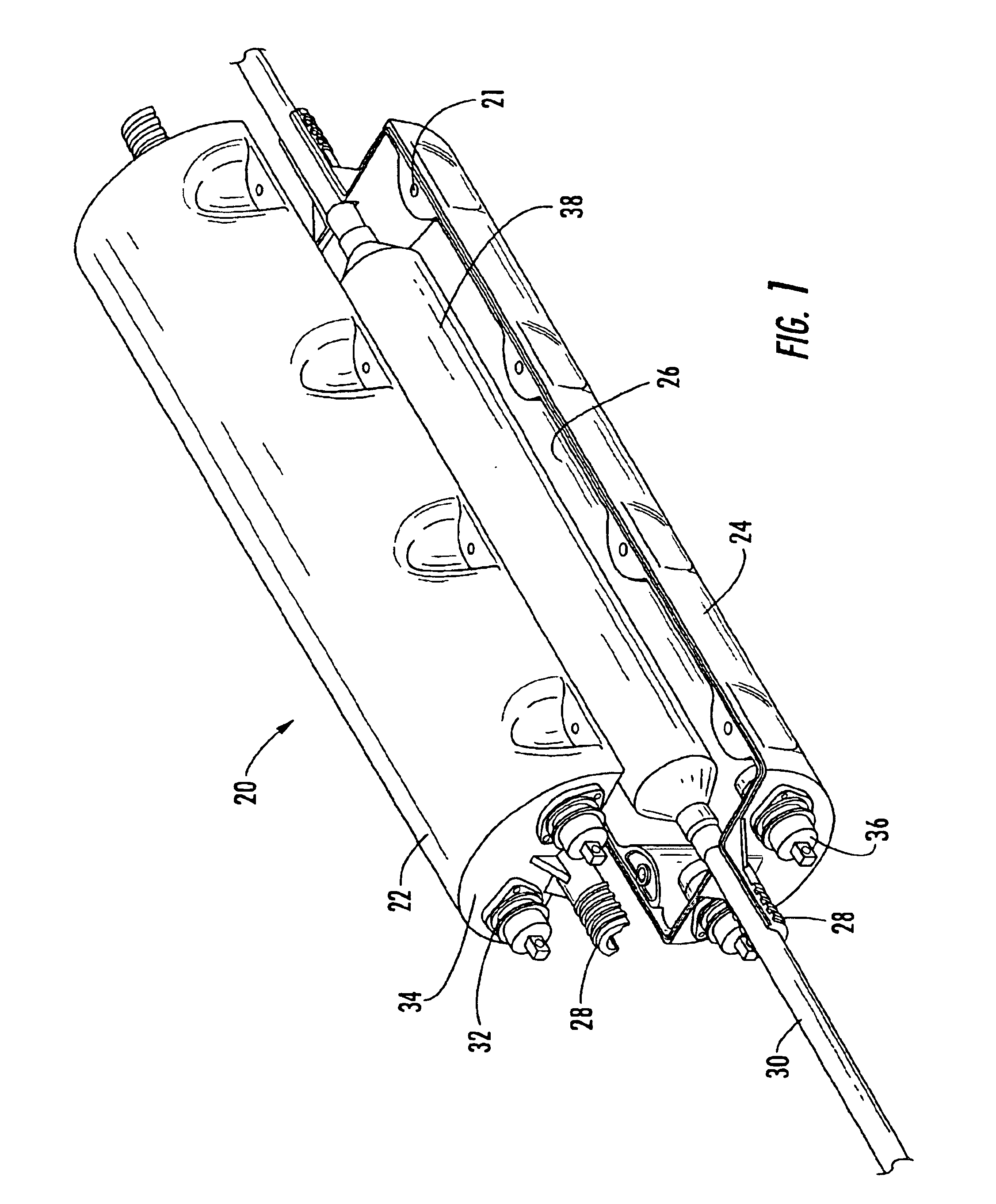
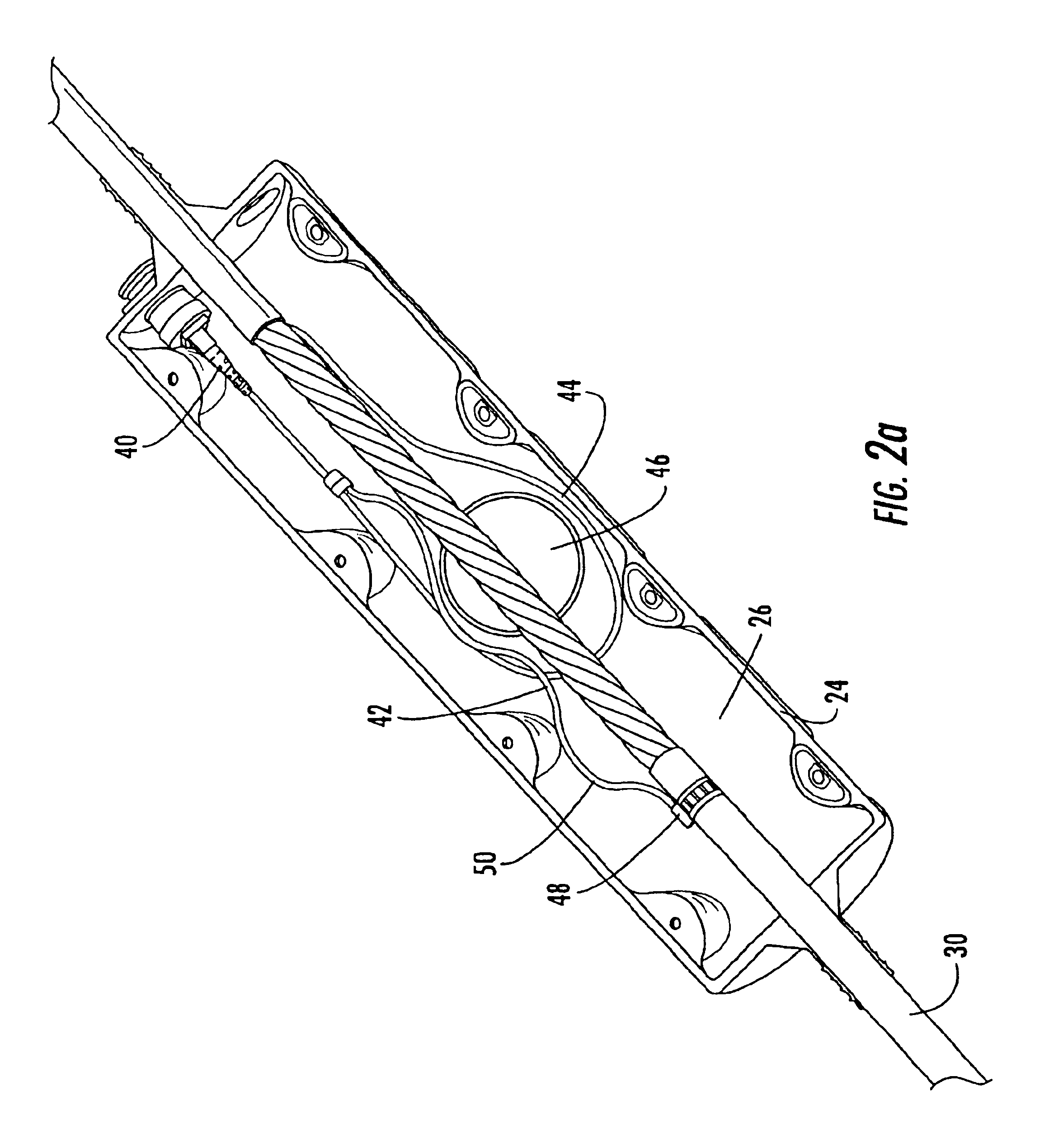
The present invention provides various embodiments of factory- and field-installed interconnection enclosures having at least one connector port through which preterminated optical connectors are accessible from the exterior of the enclosure without having to open or enter the enclosure. The various embodiments of the present invention may be applied in a “fiber-to-the-premises” (FTTP) termination system, or in any other term...


PUM


Abstract

An interconnection enclosure comprising at least one connector port operable for receiving a connector pair and a preterminated optical connector received in the at least one connector port, wherein the preterminated optical connector is adapted to be withdrawn from the exterior of the enclosure without entering the enclosure. The enclosure further comprising a tether means, a bend radius control means and a sealing means. An interconnection enclosure comprised of two halves held together by a fastening means, the enclosure defining an end wall and defining at least one connector port opening through the end wall for receiving a preterminated optical connector, the enclosure housing further defining an opening for receiving a distribution cable extending therethrough, wherein the preterminated optical connector is adapted to be withdrawn from the exterior of the enclosure without entering the enclosure.

Description

BACKGROUND OF THE INVENTION1. Field of the InventionThe present invention relates generally to an enclosure for interconnecting preterminated optical fibers, and more specifically, to an enclosure having at least one connector port and at least one preterminated fiber optic connector that provides access to the preterminated connectors from the exterior of the enclosure.2. Description of the Related ArtOptical fiber cable is used for a variety of applications including voice communications, data transmission and the like. As a result of the increase in demand, fiber optic networks typically include an ever-increasing number of access points in which one or more optical fibers are branched from a distribution cable. These access points provide an increase in the number of connections in a given area and may be used to supply “fiber-to-the-premises” (FTTP). Based on the increase in the number of access points, and based on the unique physical needs of the optical fibers themselves, an...

Claims


Application Information

Patent Timeline
IPC IPC(8): G02B6/38
CPCG02B6/3825G02B6/444G02B6/3897
Inventor ELKINS, II, ROBERT B.LUTHER, JAMES P.NIELSEN, LARS K.SZENTESI, OTTO I.TRAN, HIEU V.
Owner CORNING OPTICAL COMM LLC
Why Eureka
Try Eureka