Electronic circuit and method for testing a line

a technology of electronic circuit and line, applied in the direction of resisting/reacting/inhibiting, fault location by pulse reflection method, instruments, etc., can solve the problems of complicated implementation of such traditional electronic circuit and method, less accurate operation, and high cost, and achieve the effect of facilitating implementation and less cos

Inactive Publication Date: 2005-03-15
WI LAN INC
View PDF7 Cites 14 Cited by
  • Summary
  • Abstract
  • Description
  • Claims
  • Application Information

AI Technical Summary

Benefits of technology

Starting from that prior art it is the object of the invention to improve an electronic circuit and method for testing a line, in particular a subscriber line in that the system and method operates more accurate and implementation thereof is facilitated and made less expensive.
The usage of such a test signal and such means allows the usage of low measurement frequencies with the result that the performance, the accuracy and the measurement range is improved, because the attenuation of the line is strongly frequency dependent.
Moreover, accuracy is increased because the system according to the invention is less sensitive to noise and other disturbances present on the line. Further, implementation of the system is reasonably simple and cheap.
It is advantageous that said means of the evaluating unit comprise an adjustable delay unit for adjustably delaying the spread spectrum test signal as generated by said PRBS generator, a second D / A converter for converting the delayed test signal into an analog delayed test signal, a mixer for multiplying the analog delayed spread spectrum test signal with the analog received reflected signal and an integrator for integrating the output signal of said mixer for variable delays of said spread spectrum test signal. Said components of said means advantageously enable an analog calculation of the correlation function of the reflected signal and the delayed test signal wherein the correlation function enables assessment of the similarity of the reflected signal and the delayed test signal. The similarity of these signals allows the location of faults on the tested line or the prediction of as to whether the line is suitable for a particular application, e.g. for broadband data transmission.

Problems solved by technology

However, implementation of such traditional electronic circuits and methods is complicated and quite expensive.
Moreover, the traditional systems are very sensitive to disturbances and noise on the line with the result that they operate less accurately.

Method used


Image

  • Electronic circuit and method for testing a line
  • Electronic circuit and method for testing a line
  • Electronic circuit and method for testing a line

Examples


Embodiment Construction

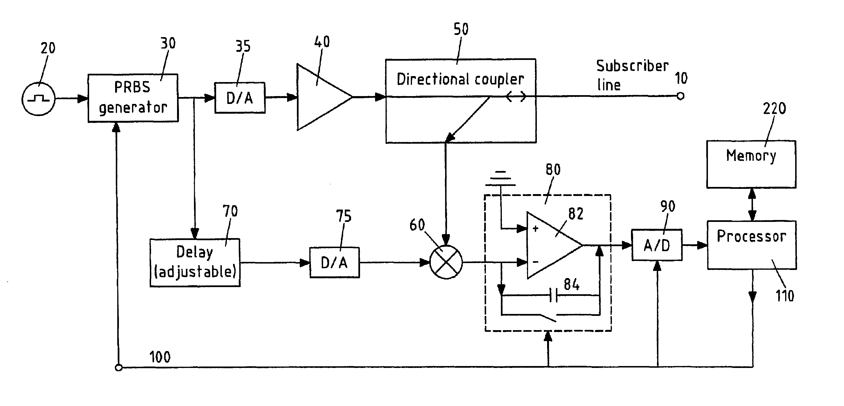
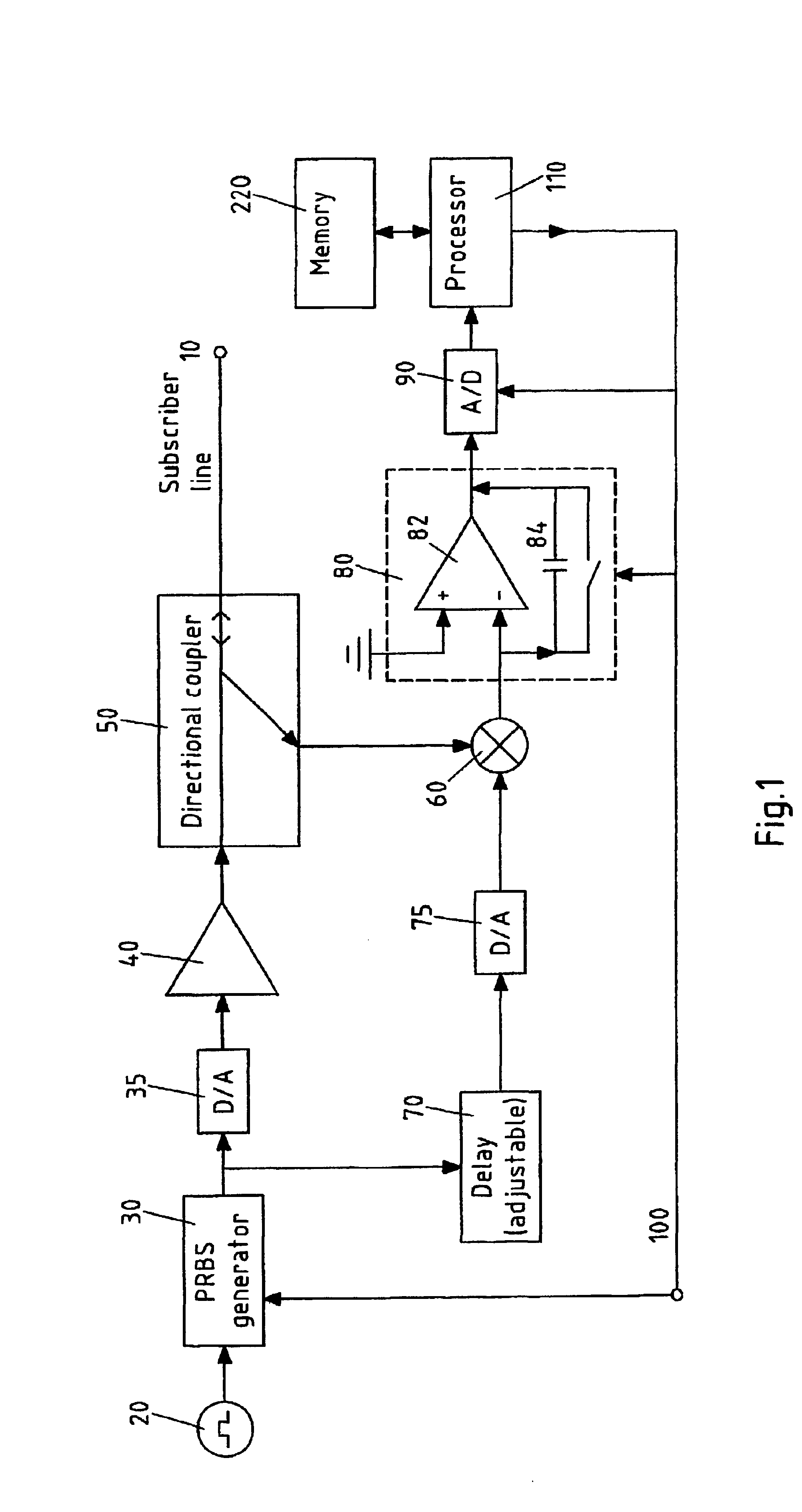
FIG. 1 shows a first embodiment of the electronic circuit according to the invention for testing a subscriber line 10. The electronic circuit comprises an adjustable clock generator 20 being coupled to a digital pseudo random bit series PRBS generator 30 for generating a PRBS-signal. The operation clock rate of the electronic circuit can be changed by changing the frequency of the clock generated by said adjustable clock generator 20.

The PRBS-signal represents a spread spectrum test signal. Said test signal is converted into an analog signal by a first digital to analog D / A converter 35 and amplified by an amplifier 40 before being output to a directional coupler 50.

The directional coupler 50 enables the transmission of said analog amplified spread spectrum test signal to said subscriber line 10 and further enables the reception of the reflected signal from said spread spectrum test signal caused by impedance discontinuities on the subscriber line 10.

Said received reflected signal i...


PUM


Abstract

The invention relates to an electronic circuit and method for testing a line (10). According to the invention the signal generator (20, 30) comprises a random bit series generating means for generating a spread spectrum test signal and the evaluating unit comprises means (60-90, 200-230) for calculating and evaluating the correlation function of the test signal and the reflected signal.

Description

FIELD OF THE INVENTIONThe invention relates to an electronic circuit for testing a line, in particular a subscriber line for broadband data transmission.TECHNICAL BACKGROUND OF THE INVENTIONSuch a circuit is known in the art and typically comprises a signal generator for generating a test signal, a coupler for coupling the signal generator to the line and for enabling a sending of said test signal to said line. The circuit further comprises an evaluating unit for receiving from said coupler a reflected signal being generated when said test signal is sent via said line.The invention further relates to a corresponding method for testing lines.In prior art in particular time domain reflectrometry was used for testing lines. According to that method a short pulse was sent to the line and a reflected signal of said short pulse was measured. Said reflected signal might be caused from any impedance discontinuities on the line. When evaluating said reflected signal, faults on the line can b...

Claims


Application Information

Patent Timeline
Patent Type & Authority Patents(United States)
IPC IPC(8): G01R31/11G01R31/08
CPCG01R31/11
Inventor ISKANIUS, MATTIPISILA, ARI-PETTERI
Owner WI LAN INC
Why Eureka
Try Eureka