Drying machine

Inactive Publication Date: 2005-04-05
LG ELECTRONICS INC
View PDF7 Cites 44 Cited by
  • Summary
  • Abstract
  • Description
  • Claims
  • Application Information

AI Technical Summary

Benefits of technology

Therefore, the present invention has been made in view of the above problems, and it is an object of the present invention to prov

Problems solved by technology

The vibration not only gives rise to harsh noise, but has a ba

Method used


Image

  • Drying machine
  • Drying machine
  • Drying machine

Examples


Example

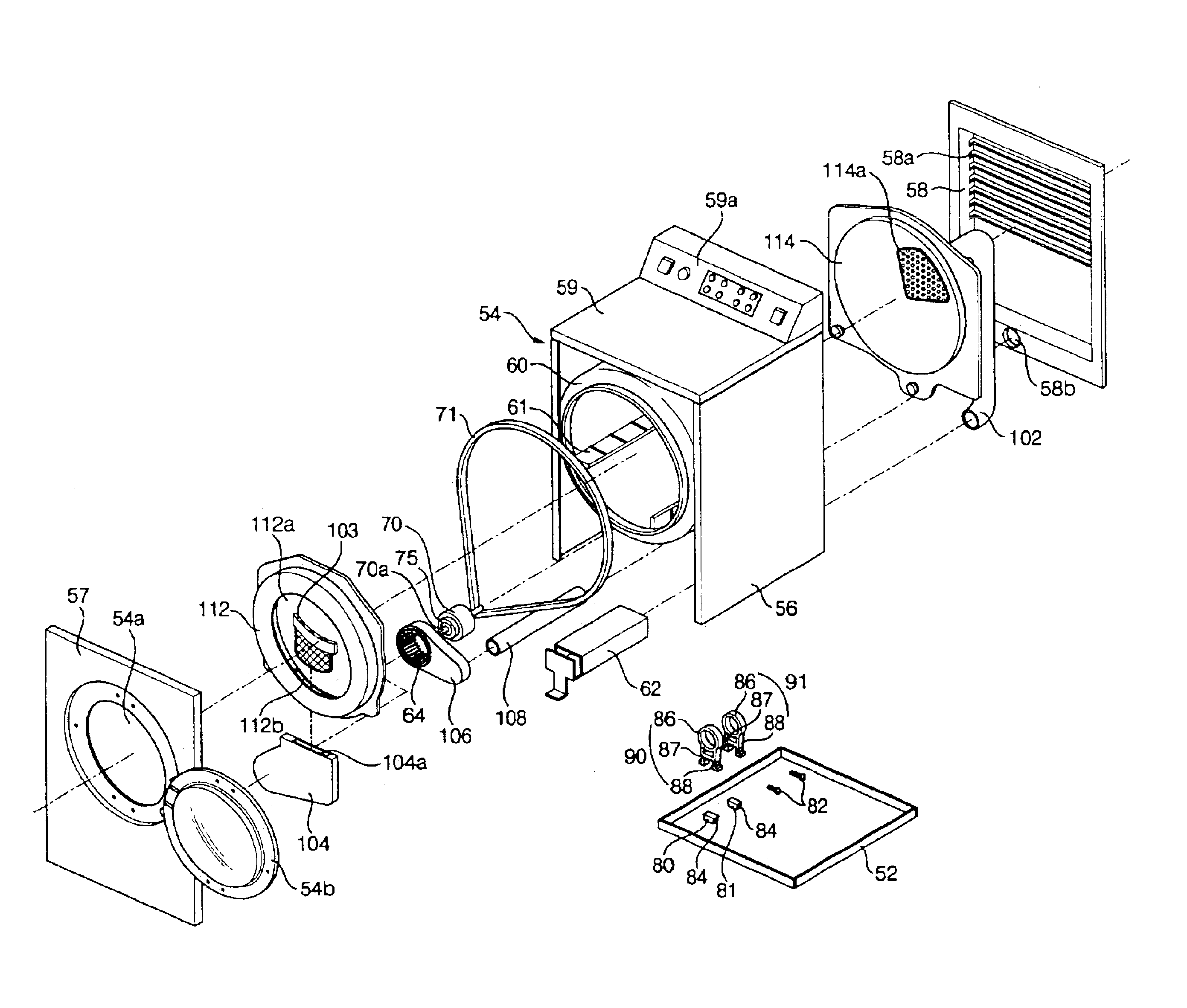
FIG. 7 is an exploded perspective view of a preferred embodiment of a drying machine according to the present invention, FIG. 8 is a perspective view, partially broken away, of the drying machine of the present invention, and FIG. 9 is a cross sectional view taken along line B—B of FIG. 8.

As shown in FIGS. 7 to 9, the drying machine according to the present invention comprises a base 52, and a casing 54 placed on the base 52. The casing 52 has a clothes inlet 54a, which also acts as a clothes outlet, formed in the front central part of the casing 52, and a door 54b pivotably attached to the casing 54. In the casing 10 is rotatably placed a drum 60. In the drying machine are provided the following: a heater 62 attached to the base 52 for heating air, a fan 64 for generating the blowing force necessary to blow the air heated by the heater 62 into the drum 60 and to discharge the air in the drum 60 to the outside of the drying machine, a motor 70 attached to the base 52 for rotating th...


PUM


Abstract

Disclosed herein is a drying machine. The drying machine comprises supporting members mounted on a base, and motor fixing brackets each including an insert part, through which a motor is inserted, and first and second supporting legs extending downwardly from the opposite ends of the insert part, the first and second supporting legs being engaged with the supporting members, whereby any vibration of the motor is prevented and attachment/detachment of the motor is easy and convenient.

Description

BACKGROUND OF THE INVENTION1. Field of the InventionThe present invention relates to a drying machine for drying clothes, etc., and more particularly to a drying machine having improved motor fixing brackets for fixing a motor securely to a base in the drying machine.2. Description of the Related ArtAs well known to those skilled in the art, a drying machine for clothes generally supplies air heated by a heater into a drum, in which clothes to be dried are put, to dry the clothes. Such a drying machine may be used independently only for drying the clothes, or incorporated with a laundry machine for washing and drying the clothes at one time.Drying machines are generally classified into an exhausting-type drying machine and a condensing-type drying machine. The exhausting-type drying machine discharges humid air used to dry clothes to the outside, while the condensing-type drying machine condenses moisture laden in humid air used to dry clothes by heat exchange with outside air to pr...

Claims


Application Information

Patent Timeline
IPC IPC(8): D06F58/08D06F58/04
CPCD06F58/08D06F37/206
Inventor HONG, KYUNG SEOPPARK, YOUNG HWANCHOI, MU YONGPARK, DAE YUN
Owner LG ELECTRONICS INC
Why Eureka
Try Eureka