Card connector having a stopper to be fixed to a mounting object and adapted to come in contact with a card inserted into the card connector

a technology of card connectors and stoppers, which is applied in the direction of connection contact materials, coupling device connections, liquid/gas/vapor treatment of propelled fabrics, etc., and can solve problems such as damage to the sealing portion of the conta

Inactive Publication Date: 2006-05-02
JAPAN AVIATION ELECTRONICS IND LTD
View PDF8 Cites 11 Cited by
  • Summary
  • Abstract
  • Description
  • Claims
  • Application Information

AI Technical Summary

Benefits of technology

[0007]It is therefore an object of this invention to provide a card connector which is suppressed in possibility of damage upon a fixing structure with respect to a mounting object even if a load applied to a card is large.

Problems solved by technology

In the existing card connector, the soldering portion of the contact may be damaged if the load applied to the card is large.

Method used


Image

  • Card connector having a stopper to be fixed to a mounting object and adapted to come in contact with a card inserted into the card connector
  • Card connector having a stopper to be fixed to a mounting object and adapted to come in contact with a card inserted into the card connector
  • Card connector having a stopper to be fixed to a mounting object and adapted to come in contact with a card inserted into the card connector

Examples


first embodiment

[0018]At first referring to FIGS. 1 to 6, description will be made of a card connector according to this invention.

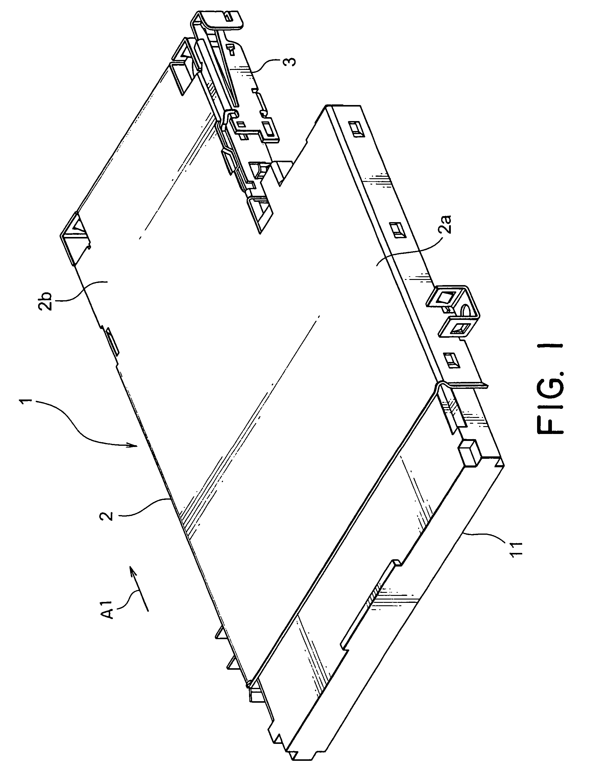
[0019]Referring to FIG. 1, a card 11 is inserted into the card connector depicted at 1 in the figure. The card connector 1 includes a cover 2 defining a card receiving portion. The cover 2 has a wide portion 2a and a narrow portion 2b. On a lateral side of the narrow portion 2b of the cover 2, an ejector 3 for ejecting the card 11 from the card connector 1 is arranged. The card 11 is analogous in shape to the cover 2.

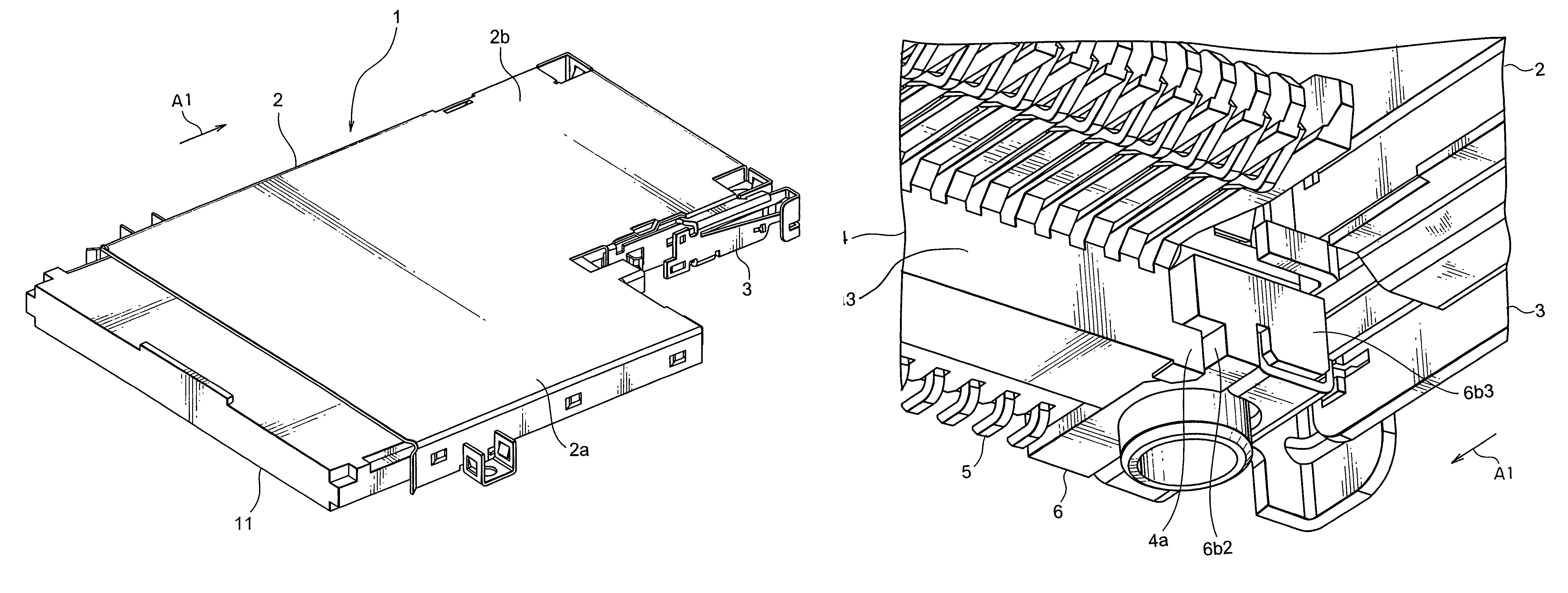
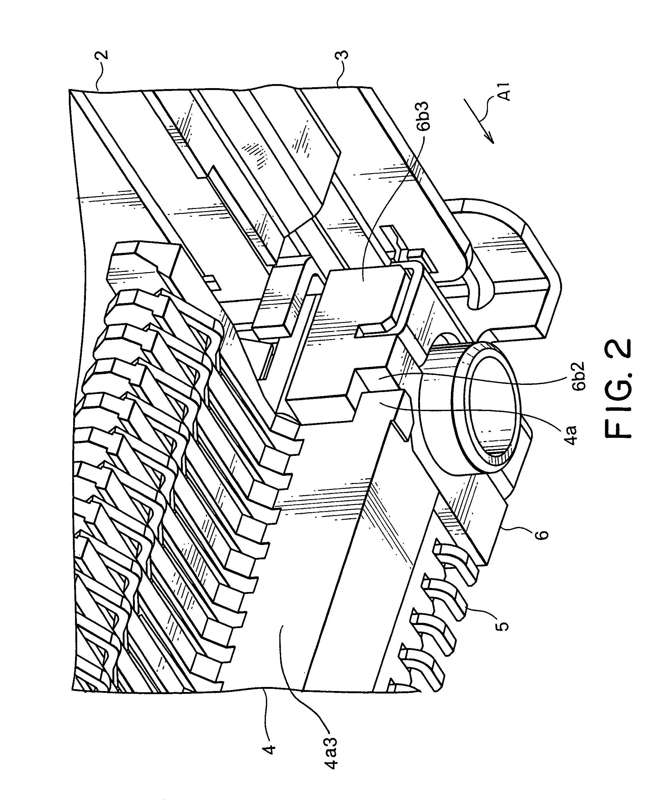
[0020]Referring to FIG. 2 together with FIG. 1, the card connector 1 has an insulator 4 holding a number of contacts 5 arranged in a single row at a predetermined pitch. A pair of stoppers 6 are arranged around opposite corners at an end of the narrow portion 2b of the cover 2. As shown in FIG. 4, each stopper 6 includes an inner stopper 6a and an outer stopper 6b coupled to the inner stopper 6a. The inner stopper 6a comprises a generally rectangular block ...

second embodiment

[0028]Referring to FIGS. 7 and 8, description will be made of a card connector according to this invention. Similar parts are designated by like reference numerals and description thereof will be omitted.

[0029]In the card connector illustrated in FIGS. 1 through 6, each of the stoppers 6 comprises two components, i.e., the inner stopper 6a and the outer stopper 6b. On the other hand, in the card connector illustrated in FIGS. 7 and 8, a stopper 7 as a whole comprises a single element. The stopper 7 has a flange 7a formed at an upper part on one side thereof. A tongue-like portion 2b2 of the narrow portion 2b of the cover 2 is engaged with a lower side of the flange 7a to prevent the cover 2 from undesirably floating or lifting up.

[0030]The stopper 7 is provided with an overhanging portion 7b formed at an upper part on the other side. If the card 11 is forced upward (in a thickness direction of the card 11), an upper surface of the card 11 is brought into contact with the overhanging...


PUM


Abstract

In a card connector to be fixed to a mounting object and used for connecting a card, a stopper is coupled to an insulator holding a conductive contact. The stopper has a fixing portion to be fixed to the mounting object. Furthermore, the stopper has a butting portion to be engaged with the card in a predetermined direction when the card is inserted in the predetermined direction into a receiving portion defined by a cover coupled to the insulator.

Description

[0001]This application claims priority to prior Japanese Patent Application JP 2004-11107, the disclosure of which is incorporated herein by reference.BACKGROUND OF THE INVENTION[0002]This invention relates to a card connector for use in connecting a card.[0003]In various types of apparatus and equipment such as a notebook-type personal computer, a PDA (personal digital assistant), and a digital camera, a card may be used for the purpose of function enhancement. In order to enable the card to be connected, the apparatus is provided with a card connector.[0004]An existing card connector comprises an insulator, a contact held by the insulator, a cover, and an ejector slidably held by the cover. The ejector has a spring and continuously urges the card in a card ejecting direction.[0005]Typically, the card connector is fixed to a mounting object, such as a printed board, to which the card connector is to be mounted. In this case, a soldering portion of the contact is soldered to the pri...

Claims


Application Information

Patent Timeline
Patent Type & Authority Patents(United States)
IPC IPC(8): H01R13/62H01R13/629H01R13/633
CPCH01R12/7094H01R12/7052D06B3/28D06B3/02
Inventor NAKAMURA, KEISUKEKIMURA, AKIRA
Owner JAPAN AVIATION ELECTRONICS IND LTD
Why Eureka
Try Eureka