Display device employing gas discharge tubes arranged in parallel between front and rear substrates to comprise a display screen, each tube having a light emitting section as part of the display screen and a cleaning section connected to the light emitting section but displaced from the display screen

a technology of gas discharge tubes and display screens, applied in the direction of discharge tubes luminescnet screens, vacuum obtaining/maintenance, gas mixture absorption, etc., can solve the problems of phosphor layer removal difficulty, discharge tubes with a volume so small, and affect discharge characteristics, etc., to prevent deterioration of discharge characteristics

Inactive Publication Date: 2006-05-23
SHINODA PLASMA
View PDF14 Cites 47 Cited by
  • Summary
  • Abstract
  • Description
  • Claims
  • Application Information

AI Technical Summary

Benefits of technology

[0011]According to the present invention, the discharge gas is kept clean by the

Problems solved by technology

However, in the gas discharge tubes applied to such display devices, it sometimes occurs that the discharge gas within the discharge tube tends to be contaminated, thereby affecting the discharge characteristics.
Namely, the discharge tubes have so small a diameter that water, carbon dioxide or the like adsorbed on surfaces of secondary electron emission layers or the phosphor layers is difficult to suffi

Method used


Image

  • Display device employing gas discharge tubes arranged in parallel between front and rear substrates to comprise a display screen, each tube having a light emitting section as part of the display screen and a cleaning section connected to the light emitting section but displaced from the display screen
  • Display device employing gas discharge tubes arranged in parallel between front and rear substrates to comprise a display screen, each tube having a light emitting section as part of the display screen and a cleaning section connected to the light emitting section but displaced from the display screen
  • Display device employing gas discharge tubes arranged in parallel between front and rear substrates to comprise a display screen, each tube having a light emitting section as part of the display screen and a cleaning section connected to the light emitting section but displaced from the display screen

Examples


Embodiment Construction

[0027]These and other objects of the present application will become more readily apparent from the detailed description given hereinafter. However, it should be understood that the detailed description and specific examples, while indicating preferred embodiments of the invention, are given by way of illustration only, since various changes and modifications within the spirit and scope of the invention will become apparent to those skilled in the art from this detailed description.

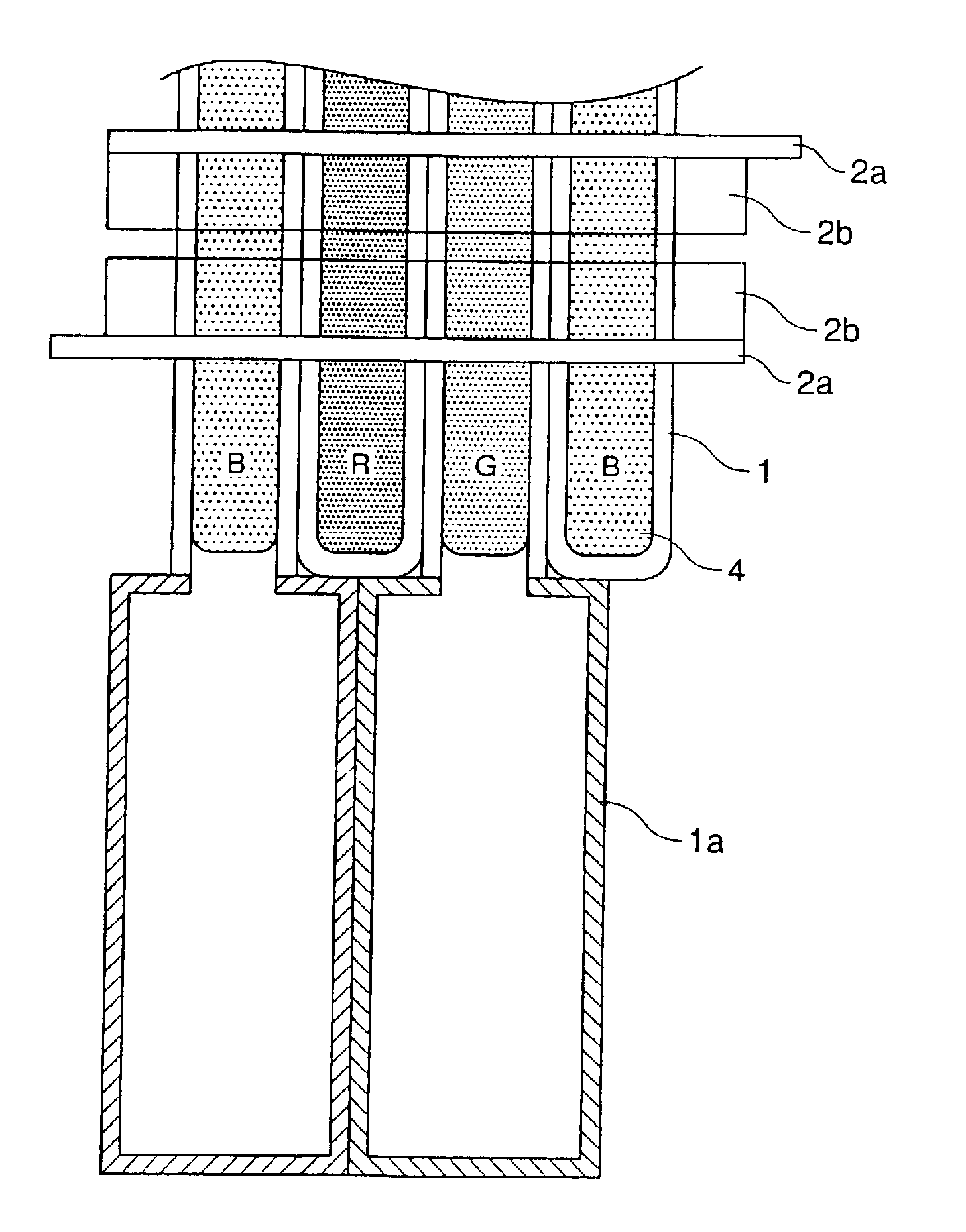
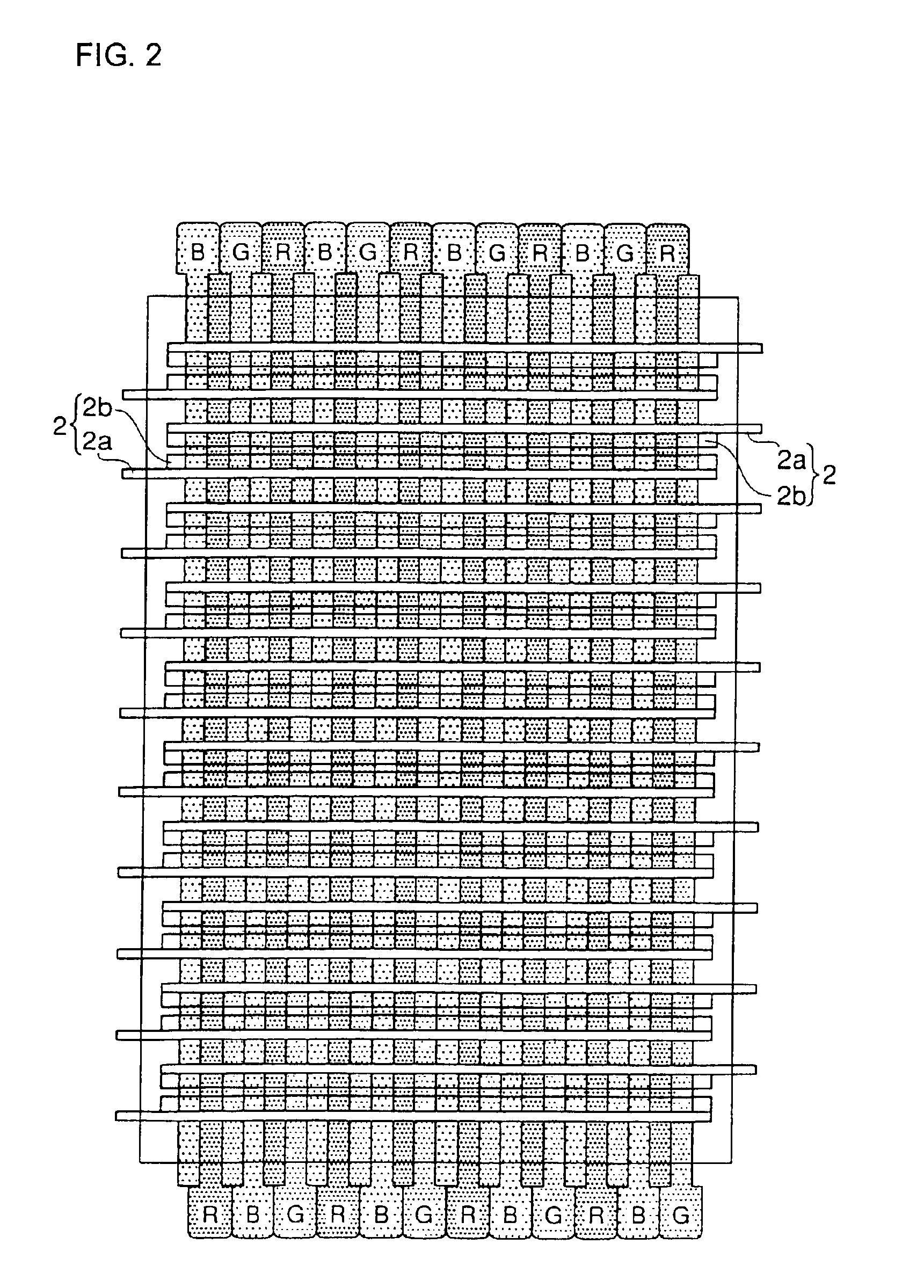
[0028]In the present invention, the phosphor layer, electrode and discharge gas can be any if they are known in the art. The light-emitting section can be any if it is constituted by the elongated tubes and emits light by electric discharges between the electrodes. The phosphor layer is formed within the elongated tube. The electrodes may be disposed either inside or outside the elongated tubes. The discharge gas is enclosed in the elongated tube.

[0029]The cleaning section may be filled with the same disc...


PUM


Abstract

A gas discharge tube has a phosphor layer formed and a discharge gas enclosed within an elongated tube which is to serve as the gas discharge tube. The gas discharge tube includes a light-emitting section and a cleaning section for cleaning the discharge gas. The cleaning section is connected to the light-emitting section.

Description

CROSS-REFERENCE TO RELATED APPLICATION[0001]This application is related to Japanese application No. 2001-400733 filed on Dec. 28, 2001, whose priority is claimed under 35 USC §119, the disclosure of which is incorporated by reference in its entirety.BACKGROUND OF THE INVENTION[0002]1. Field of the Invention[0003]The present invention relates to a gas discharge tube. More particularly, it relates to a gas discharge tube preferably applied to a display device in which the gas discharge tubes, made of elongated tubes, of a diameter of about 0.5 to 5 mm are arranged parallel to each other to constitute a display screen.[0004]2. Description of Related Art[0005]In general, PDPs (plasma display panels), known as panels for large-scale display, are so constructed that a pair of substrates each having electrodes formed thereon are disposed opposite to each other with a periphery thereof sealed and a discharge gas enclosed in a discharge space defined between the substrate pair. Apart from su...

Claims


Application Information

Patent Timeline
IPC IPC(8): H01J17/49H01J61/30H01J61/26H01J9/38H01J11/10H01J11/12H01J11/18H01J11/24H01J11/26H01J11/42H01J11/44H01J11/50H01J11/52H01J61/94H01J65/00
CPCH01J11/18H01J9/38H01J11/10
Inventor TOKAI, AKIRAYAMADA, HITOSHIISHIMOTO, MANABUSHINODA, TSUTAE
Owner SHINODA PLASMA
Why Eureka
Try Eureka