Acoustic coupling with a fluid retainer

a fluid retainer and acoustic coupling technology, applied in the direction of instruments, specific gravity measurement, magnetic property measurement, etc., can solve the problems of inoperable machines or parts, inability to fully meet the needs of the time, and failure of laminates

Inactive Publication Date: 2006-06-06
METABCAN TECH
View PDF26 Cites 12 Cited by
  • Summary
  • Abstract
  • Description
  • Claims
  • Application Information

AI Technical Summary

Problems solved by technology

If a structure, such as a machine or a part of a product, has a defect, such as a crack, a void, or a recess, there is a risk that the machine or part will become inoperable due to the defect.
In addition to concerns about delamination due to voids, laminates can also fail due to cracks.
Thus, a heretofore-unaddressed need exists in the industry to address the aforementioned deficiencies and inadequacies.

Method used


Image

  • Acoustic coupling with a fluid retainer
  • Acoustic coupling with a fluid retainer
  • Acoustic coupling with a fluid retainer

Examples


Embodiment Construction

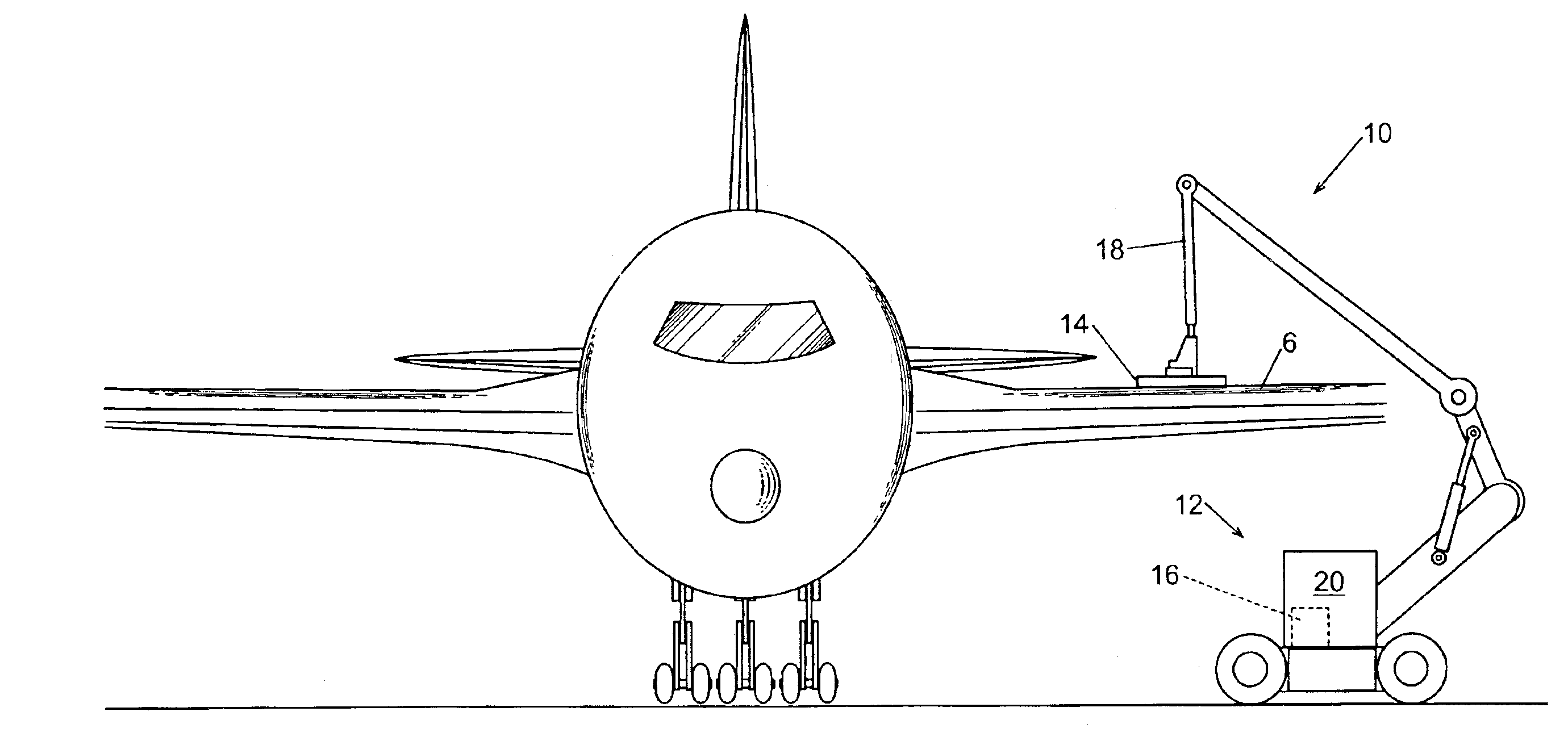
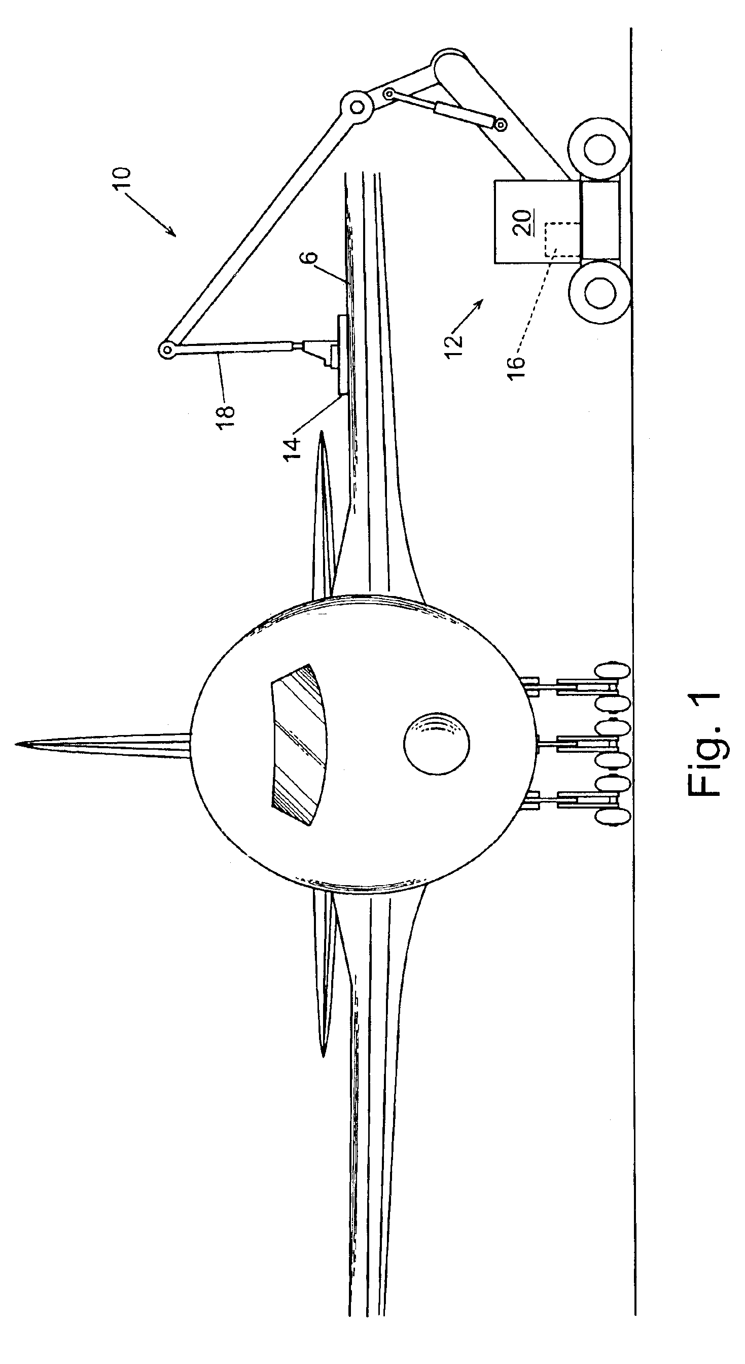
[0021]Referring to FIG. 1, a moveable acoustic scanning system (MASS) 10 is used to scan the skin 6 of an aircraft 8. The MASS 10 includes an acoustic scanning assembly (ASA) 14 attached to a positioning apparatus 12. The positioning apparatus 12 includes a base 20 and an extendable arm 18 that extends from base 20. The positioning apparatus includes a control system 16, which is typically a computer, or the like, that is used for, among other things, controlling arm 18. In one preferred embodiment, the base 20 is moveable so that the arm 18 can be readily moved around the aircraft 8 and positioned near subsequent aircraft. Non-limiting examples of a moveable base include but are not limited to trucks, trolleys, carts, scissor-jack, sky-jacks, and hand cars. With the arm 18 positioned proximal to the aircraft 8, the arm 18 is used to position the ASA 14 proximal to selected portions of the aircraft 8. In one preferred embodiment, the arm 18 is adapted to move in three-dimensions so ...


PUM

PropertyMeasurementUnit
frequencyaaaaaaaaaa
lengthaaaaaaaaaa
frequencyaaaaaaaaaa

Abstract

An apparatus examines the internal structure of an object disposed substantially in a medium such as air, which essentially totally reflects acoustic signals in the 1-200 MHz frequency range. The apparatus has an acoustic transducer that emits and receives acoustic signals in the 1-200 MHz frequency range and an acoustic coupler that acoustically couples the acoustic transducer to the object. The acoustic coupler is adapted to essentially retain a body of fluid such as water between a section of the surface of the object and the acoustic transducer. The fluid carries acoustic signals in the 1-200 MHz frequency range between the acoustic transducer and the object.

Description

CROSS-REFERENCE TO RELATED APPLICATION[0001]This application claims priority to co-pending U.S. provisional applications entitled: “Scanning Acoustic Microscopy,” having Ser. No. 60 / 355,201, filed Feb. 8, 2002, which is entirely incorporated by reference; “Acoustic Coupling,” having Ser. No. 60 / 355,649, filed Feb. 8, 2002, which is entirely incorporated by reference; and “Apparatus For Reflection Mode Acoustic Microscopy Scanning Of An Object,” having Ser. No. 60 / 378,450, filed May 7, 2002. This application is one of five co-pending, commonly assigned U.S. patent applications all of which have the same filing date of May 31, 2002. The other co-pending Applications are entitled “Flowing Fluid Acoustic Coupling,” Ser. No. 10 / 159,585; “Scanning Acoustic Microscopy,” Ser. No. 10 / 159,547; “Acoustic Coupling With A Fluid Bath,” Ser. No. 10 / 160,493; and “Non-Fluid Acoustic Coupling,” Ser. No. 10 / 191,044, and all of the above-mentioned co-pending applications are hereby incorporated into th...

Claims


Application Information

Patent Timeline
Patent Type & Authority Patents(United States)
IPC IPC(8): G01N29/04G01N29/00G01N29/26G01N29/265G01N29/28
CPCG01N29/265G01N29/28G01N2291/2694G01N2291/101G01N2291/044
Inventor MUELLER, DENNIS WILLIAM
Owner METABCAN TECH
Why Eureka
Try Eureka