Fuel injectors and methods of fuel injection

Active Publication Date: 2006-09-19
STURMAN INDS
View PDF15 Cites 28 Cited by
  • Summary
  • Abstract
  • Description
  • Claims
  • Application Information

AI Technical Summary

Problems solved by technology

While control valves of the foregoing type can be made relatively small and fast-acting, control of actuation fluid in this manner for direct fuel injection has certain limitations.
Consequently, intensification on actuation of the control valve(s) requires significant actuation fluid flow, and is therefore less than immediate.
Also, this flow requirement sets the minimum size for the electrically operated control valves, and further requires de-intensification between injection events, making multiple injections during a single injection event difficult and energy consuming.

Method used


Image

  • Fuel injectors and methods of fuel injection
  • Fuel injectors and methods of fuel injection
  • Fuel injectors and methods of fuel injection

Examples


Embodiment Construction

[0020]FIG. 1 is a perspective view of one embodiment of fuel injector in accordance with the present invention. The major parts of the fuel injector visible in this figure are the injection tip or nozzle, generally indicated by the numeral 20, a lower injector body assembly body 22, and upper injector body assembly 24, and a control module 26.

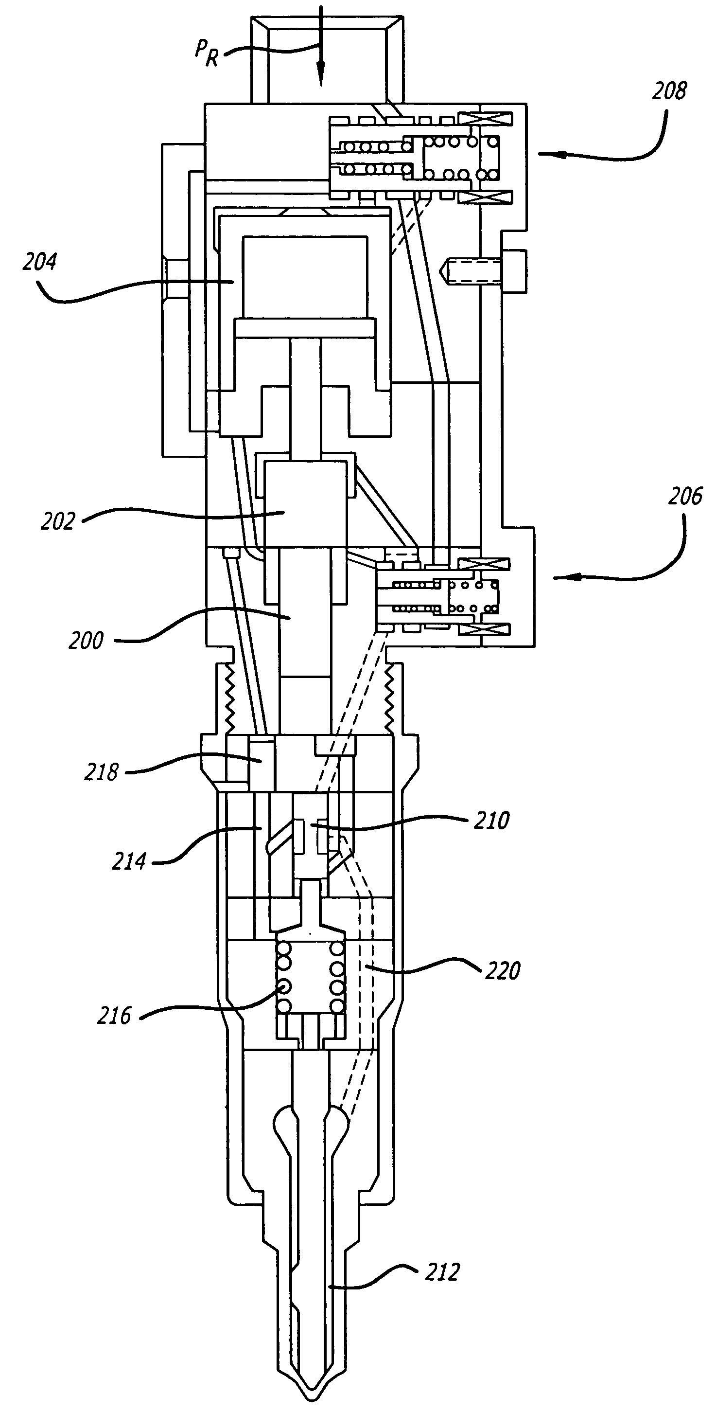
[0021]FIG. 2 presents a cross-section of the injector of FIG. 1 illustrating the cooperation of the injection tip 20, the various parts of the lower injection body assembly 22 and the upper injector body assembly 24. FIGS. 3 and 4 show the same cross-sections of the upper injector body assembly and the lower injector body assembly, respectively, on a larger scale. As illustrated in FIG. 3, the upper injector body assembly 24 is comprised of an intensifier piston 26 operative to provide a high or intensified pressure to the fuel in the intensifier chamber 28 in response to a downward force on the intensifier piston. The intensifier piston 26 may...


PUM


Abstract

Fuel injectors and methods of fuel injection allowing direct control of the flow of fuel at an intensified pressure to the needle. A valve, typically a spool valve, is placed in the fuel passage between the intensifier actuation piston and the needle, and controlled by a control valve which may be independent of the control valve controlling the coupling of actuation fluid and a vent to the intensifier actuation piston. This allows achievement of intensification before initiating injection, and control of multiple injections in a single injection event while maintaining fuel intensification throughout the duration of the injection event. Various embodiments are disclosed, including embodiments having multiple intensifiers, having control of pressure over the needle, having two stage control valve systems for control of intensifier actuation fluid, and combining control of one of the intensifiers and the valve controlling flow of intensified fuel to the needle for injection.

Description

CROSS-REFERENCE TO RELATED APPLICATION[0001]This application claims the benefit of U.S. Provisional Patent Application No. 60 / 475,022 filed May 30, 2003 and U.S. Provisional Patent Application No. 60 / 485,948 filed Jul. 7, 2003.BACKGROUND OF THE INVENTION[0002]1. Field of the Invention[0003]The present invention relates to the field of fuel injectors, and more particularly to intensifier type fuel injectors.[0004]2. Prior Art[0005]Intensifier type fuel injectors are well known in the prior art. As an example, see U.S. Pat. No. 5,460,329. That patent discloses an electromagnetically actuated spool valve for controlling the coupling of an area over an intensifier piston to an actuating fluid under pressure or to a vent, the intensifier piston driving a smaller piston to intensify the pressure of fuel for injection purposes. While various types of valves are known for use with such injectors, the valves generally control the flow of actuation fluid to and from the area over intensifier ...

Claims


Application Information

Patent Timeline
IPC IPC(8): F02M47/02F02M59/00F02M57/02F02M59/10
CPCF02M47/027F02M57/025F02M59/105
InventorSTURMAN, ODED E.
OwnerSTURMAN INDS