Panel fastener system

a technology of fastener and panel, applied in the field of fasteners, can solve the problems of difficult to properly locate and weld the fastener nut over the opening in the panel, and the fastener nut is not easy to install, and achieves the effect of weight and significant cost savings

Inactive Publication Date: 2006-10-31
ILLINOIS TOOL WORKS INC
View PDF24 Cites 1 Cited by
  • Summary
  • Abstract
  • Description
  • Claims
  • Application Information

AI Technical Summary

Benefits of technology

[0006]The present invention is directed to a fastener system that attaches easily to a panel. The fastener system of the invention includes a fastener nut that twists into an opening in the panel. A fastener bolt may then be threaded onto the fastener nut to mount a component or device to the panel. Once installed onto the panel, the fastener nut will not back-out of the opening in the panel when the fastener bolt is removed. Importantly, the fastener system of the present invention is more easily installed than known panel fasteners. The fastener system also provides weight and significant cost savings over fasteners that are welded or press fitted onto the panel.

Problems solved by technology

Problems exist, however, with respect to welding fastener nuts onto panels.
For instance, it is often difficult to properly locate and weld the fastener nut over the opening in the panel.
In addition, it is often difficult to consistently and completely weld the nut onto the panel.
Moreover, a large capital investment is required for equipment that will accurately locate and completely weld the fastener nut onto the panel.
For example, one known drawback with the force fitting technique is the potential for the panel to yield or deform under the force applied to the panel.
In addition, as with the welding technique, the press fitting technique requires a large capital investment in equipment, such as hydraulic presses to press the fastener onto the panel.
Still another drawback with this technique is that once the fastener is pressed into the panel opening, the fastener will back out or become detached from the panel upon the application of relatively low torque forces.

Method used


Image

  • Panel fastener system
  • Panel fastener system
  • Panel fastener system

Examples


Embodiment Construction

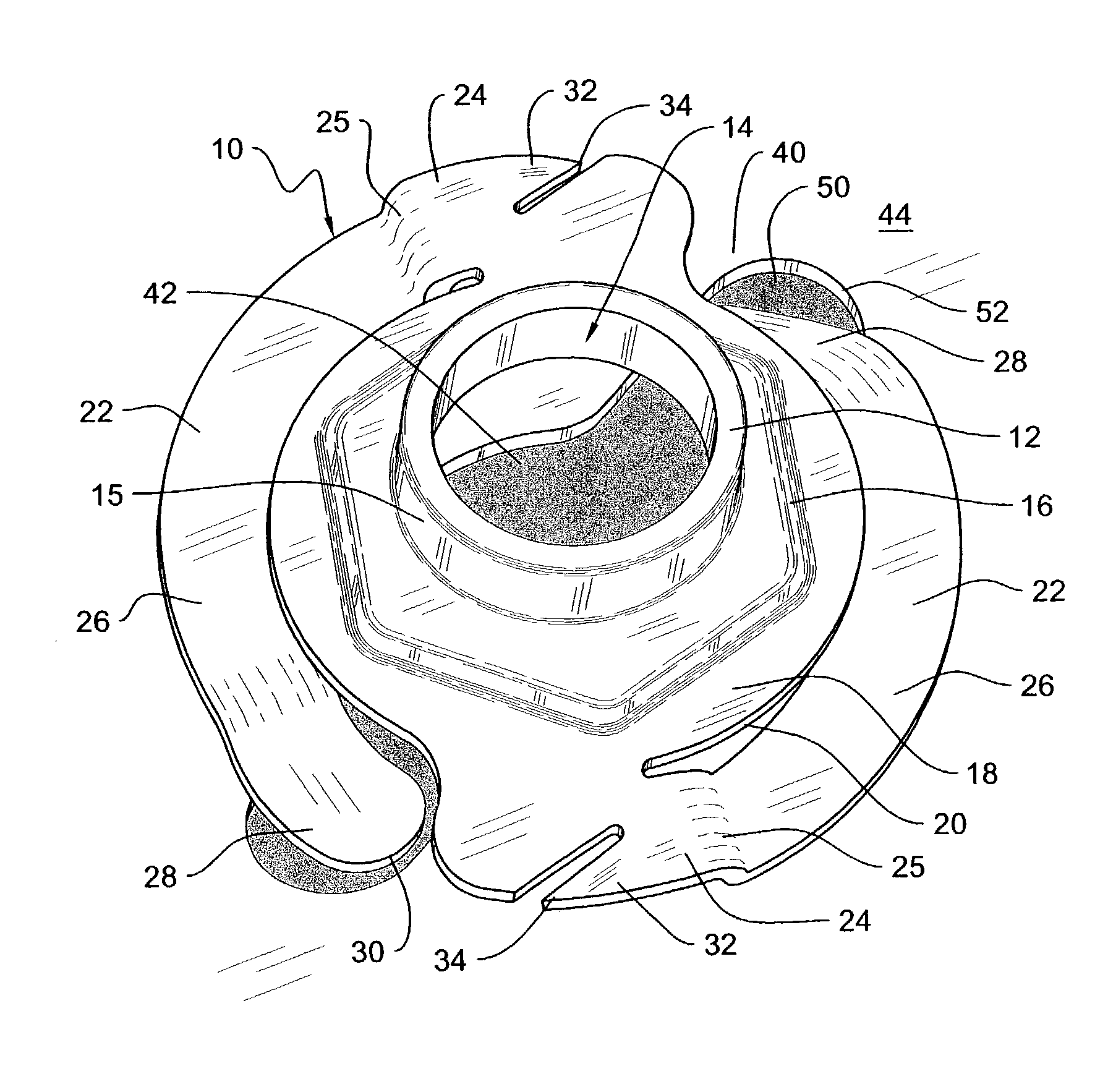
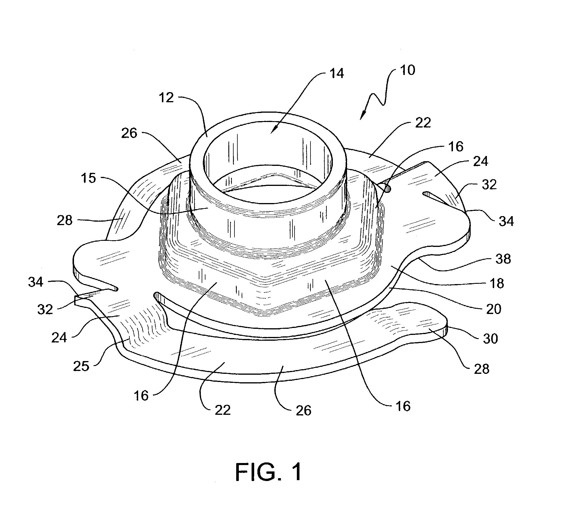
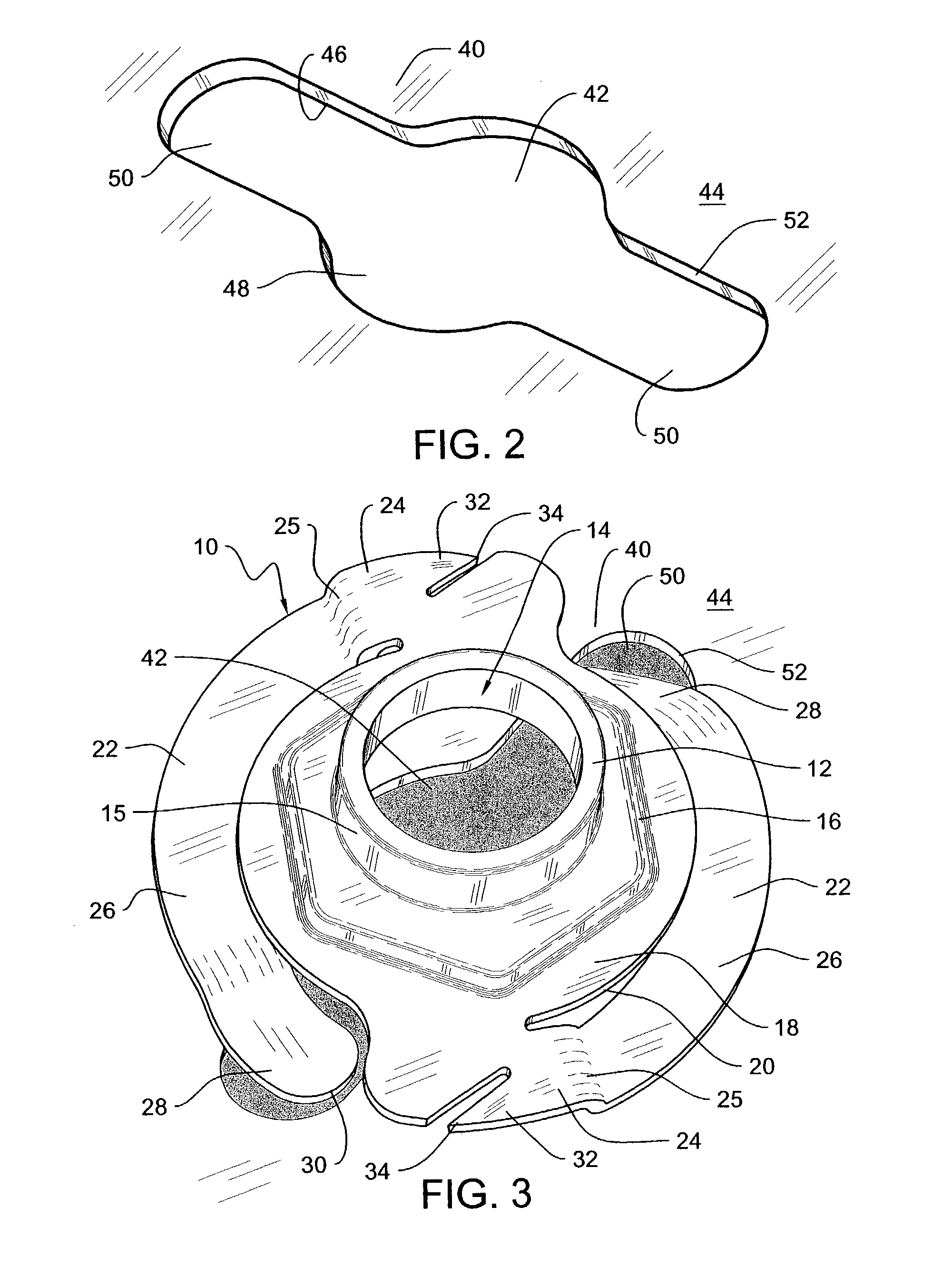
[0013]Referring to FIGS. 1 and 2, in one embodiment, the fastener system of the present invention includes a fastener 10 depicted as a fastener nut. The fastener 10 is configured to mount to an opening 42 in a panel 40, as described below, and to receive a mating fastener through the panel opening 42 to mount components onto the panel 40. It should be understood that while the present invention is illustrated in the form of a fastener nut, the teachings of the invention may be embodied in the form of other types of fasteners or fastener components, including a bolt, screw, rod or similar fastener.

[0014]Referring to FIG. 1, in one embodiment, the fastener 10 includes a fastener body 12 defining a hole 14 extending through the fastener body 12. The hole 14 is formed by a cylindrical wall 15 and is configured to receive a mating fastener, not shown, to mount components onto the panel 40. The fastener body 12 further defines a plurality of facets 16 arranged in a hexagon around the peri...


PUM


Abstract

A fastener system for mounting to a panel includes a twist-in fastener that rotatably engages an opening in the panel. The fastener includes a fastener body defining an opening extending through the fastener body for receiving a mating fastener, a plurality of facets positioned around the fastener body opening for facilitating the mounting of the fastener onto the panel, and a fastener base. Panel-engaging members extend outwardly from the fastener base to rotatably mount the fastener through the panel opening and onto the panel. At least one anti-rotation member also extends outwardly from the fastener base to prevent the mounted fastener from backing out of the panel opening upon the removal of the mating fastener.

Description

CROSS REFERENCE TO RELATED APPLICATION[0001]This Non-Provisional Application claims benefit to U.S. Provisional Application Ser. No. 60 / 411,061 filed Sep. 16, 2002.FIELD OF THE INVENTION[0002]The present invention relates generally to fasteners and more particularly to panel fasteners that are used to secure items to panels.BACKGROUND OF THE INVENTION[0003]It is known to use panel fasteners for various applications. Conventional panel fasteners include a threaded nut that is anchored over an opening in a panel, and a bolt that is engageable with the threaded nut to secure a component or device to the panel. Typically, the threaded nut of the fastener is welded onto the panel and over the opening in the panel. Problems exist, however, with respect to welding fastener nuts onto panels. For instance, it is often difficult to properly locate and weld the fastener nut over the opening in the panel. In addition, it is often difficult to consistently and completely weld the nut onto the pa...

Claims


Application Information

Patent Timeline
Patent Type & Authority Patents(United States)
IPC IPC(8): F16B37/02F16B21/02F16B37/04
CPCF16B21/02F16B37/042
Inventor JOHNSON, LAWRENCE W.KOSIDLO, JOHN M.
Owner ILLINOIS TOOL WORKS INC
Why Eureka
Try Eureka