Indicating device

a technology of indicating device and counting device, which is applied in the direction of inhalator, packaging, instruments, etc., can solve the problems of complex moving parts, high manufacturing cost, and easy to be easily affected by counting inaccuracy, so as to simplify the manufacturing and assembly process, reduce the ratio of gears, and improve the accuracy of counting devices

Inactive Publication Date: 2006-12-05
TRUDELL MEDICAL INT INC
View PDF12 Cites 18 Cited by
  • Summary
  • Abstract
  • Description
  • Claims
  • Application Information

AI Technical Summary

Benefits of technology

[0018]The present invention provides significant advantages over other indicating devices. In particular, with respect to the first embodiment of the indicating device, the worm provides for a compact drive component that does not occupy excess space within the housing. Moreover, the worm provides for high gear reduction ratios while maintaining a continuous engagement with the circular worm gear. The continuous engagement of the worm and circular gear ensures that the accuracy of the counting device is maintained, while simultaneously simplifying the manufacturing and assembly process.
[0019]The use of a circular gear having an axis non-parallel, and preferably transverse or perpendicular to the longitudinal movement of the container within the housing, also provides several advantages. Importantly, the gear can be easily mounted to the housing with an inexpensive and easy-to-install axle. Thus, the circular gear provides for a compact single-cycle device that fits easily into the housing, and which maintains continuous engagement with the worm gear for improved and accurate indexing of the indicator member. Moreover, the components are arranged so as to not interfere with or otherwise impede the air flow from the valve stem to the exhaust port of the housing. In addition, the indicator wheel, which is preferably coaxially mounted with the worm gear, provides an ideal planar surface for displaying the dosage indicia. The indicia can be easily viewed by the user through the viewing window.
[0020]The second embodiment of the indicating device provides similar advantages. In particular, the plurality of indicator members can be mounted in a compact arrangement to provide accuracy and reliability under various operating conditions but which does not impede or obstruct the airflow to the user. Moreover, the various parts are relatively inexpensive to manufacture and assemble. The indicia, which are visible to the user through the viewing window, are easy to read and readily accessible to the user.
[0021]The indicator module, with any of the various embodiments of indicating assemblies disposed therein, also presents several advantages. In particular, the self-contained unit can be separately manufactured and installed as needed in any number of conventional types of dispensing devices with minimal modification thereof. Moreover, the module can be easily installed without interfering with or otherwise impeding the air flow from the valve stem to the exhaust port and ultimately to the user.
[0022]The key member also presents several advantages. In particular, differently configured key members and passageways can be installed between containers holding different substances such as medicaments and corresponding delivery system housings so as to prevent the user from interchanging various containers and housings so as to thereby alter the number of doses being counted. The key member and passageway can also prevent a user from using the wrong delivery system for a particular container having a particular substance, such as a medicament.

Problems solved by technology

For example, indicating devices of this nature may include complex moving parts which can be difficult to assemble and expensive to manufacture.
Such devices may also be susceptible to counting inaccuracies due to the configuration of the indexing or mating parts, or require excessive amounts of space within the housing to accommodate the relatively large or numerous moving parts.
Others still may impede or interfere with the airflow and medicament being dispensed from the inhalation device.
Such devices can be relatively expensive to manufacture, however, and typically require a power source which may be susceptible to damage in various environments, such as moist conditions.

Method used


Image

  • Indicating device
  • Indicating device
  • Indicating device

Examples


Embodiment Construction

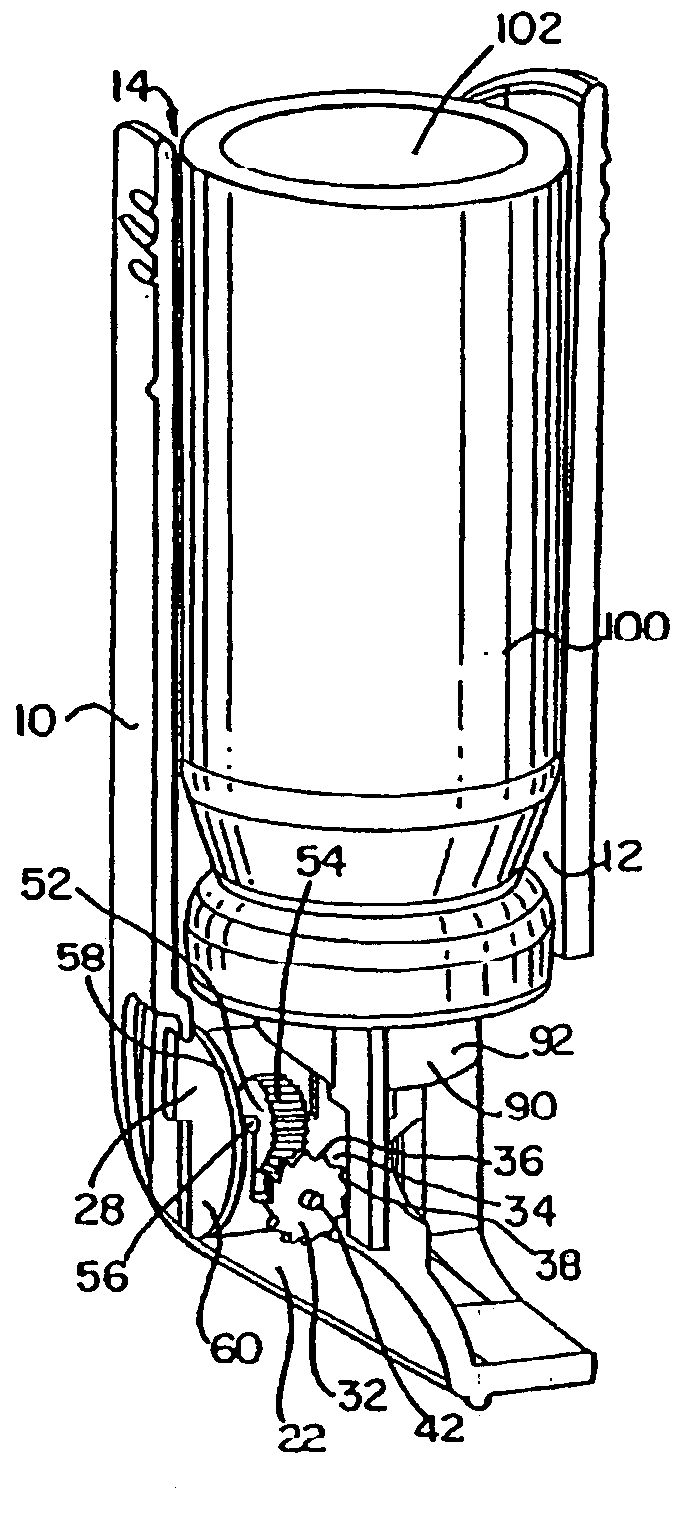
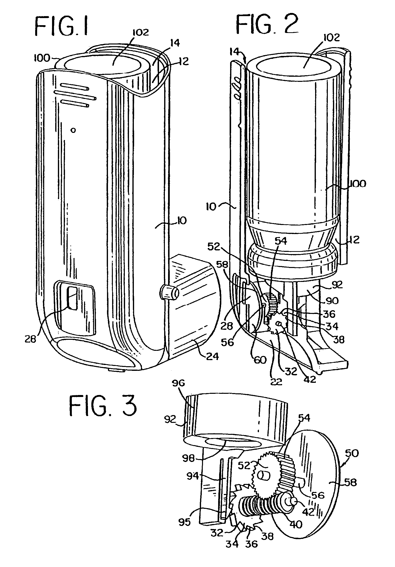
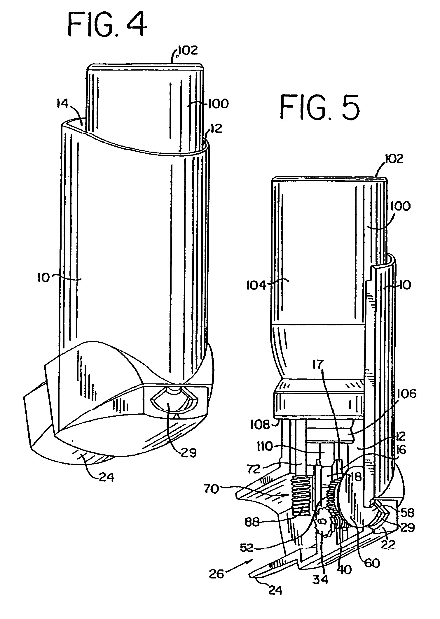
[0072]Referring to the drawings, and in particular FIGS. 1, 4, 6, 7 and 24, a delivery system, configured as a dispensing device, or dispenser, is shown as including a housing 10, or actuator boot, and a container 100 disposed therein. The housing 10 has a longitudinally extending cavity 12 shaped to receive the container. A top portion of the housing is generally open such that the container can be inserted in the housing through opening 14 and be installed therein with a bottom end 102 of the container protruding from the housing and exposed to the user for actuation.

[0073]It should be understood that the term “delivery system,” as used herein, is meant to include a system or apparatus for delivering a substance from a container, reservoir, or similar repository, to a user, and includes but is not limited to the disclosed dispensing device, which delivers the substance to the user in the form of an aerosol that is inhaled by the user. The term “dispensing device,” as used herein, ...


PUM


Abstract

A device for dispensing metered dosages of a substance from a container includes a dispenser housing having a longitudinally extending cavity defined at least in part by a wall and a support block spaced from the wall. The container is disposed in the cavity of the dispenser housing and is container reciprocally moveable within the dispenser housing along a longitudinal axis. An indicating device is disposed in the dispenser housing and includes an annular member disposed around a first end of the container with a valve stem of the container extending beyond the annular member. The indicating device includes at least one indicator member rotatable about an axis of rotation. At least a portion of the indicating device is fixedly connected to the container and is reversibly removable with the container from the dispenser housing.

Description

[0001]This application is a continuation of U.S. application Ser. No. 11 / 287,818, filed Nov. 28, 2005, which is a continuation of U.S. application Ser. No. 10 / 865,531, filed Jun. 10, 2004, now U.S. Pat. No. 6,997,349, which is a continuation of U.S. application Ser. No. 10 / 369,091, filed Feb. 18, 2003, now U.S. Pat. No. 6,938,796, which is a continuation of U.S. application Ser. No. 10 / 193,508, filed Jul. 11, 2002, now U.S. Pat. No. 6,561,384, which is a continuation of U.S. application Ser. No. 09 / 954,428, filed Sep. 14, 2001, now U.S. Pat. No. 6,435,372, which is a continuation of U.S. application Ser. No. 09 / 704,959, filed Nov. 2, 2000, now abandoned, which is a division of U.S. application Ser. No. 09 / 149,708, filed Sep. 8, 1998, now U.S. Pat. No. 6,161,724, which application is a continuation-in-part of U.S. application Ser. No. 09 / 008,184, filed Jan. 16, 1998, now U.S. Pat. No. 6,142,339, the entire disclosures of which are hereby incorporated herein by reference. No license, ...

Claims


Application Information

Patent Timeline
Patent Type & Authority Patents(United States)
IPC IPC(8): B67D5/06A61J3/06A61M11/00A61M15/00B67D7/06B67D7/22B67D7/56G06M1/04G06M1/08G06M1/16
CPCA61M15/009G06M1/041G06M1/083A61M15/0065A61M15/0068A61M15/0075A61M15/0076G06M1/163A61M15/0071A61M15/0021A61M15/0081
Inventor BLACKER, RICHARDENGELBRETH, DANIEL K.SCHMIDT, JAMES N.
Owner TRUDELL MEDICAL INT INC
Why Eureka
Try Eureka