Impact-absorbing barrier assembly

a technology of impact-absorbing barriers and assemblies, which is applied in roadway safety arrangements, roads, construction, etc., can solve the problems of difficult to see how traffic is being redirected, many inherent limitations, and barriers that are difficult to absorb and achieve the effect of advantageously dissipating the impact energy generated by vehicles during collisions

Inactive Publication Date: 2006-12-05
MALLINSON CYRUS J +1
View PDF18 Cites 33 Cited by
  • Summary
  • Abstract
  • Description
  • Claims
  • Application Information

AI Technical Summary

Benefits of technology

[0014]In view of the foregoing background, it is therefore an object of the present invention to provide an impact-absorbing barrier assembly. These and other objects, features, and advantages of the invention are provided by a barrier assembly for effectively absorbing and advantageously dissipating impact energy generated by a vehicle during a collision.

Problems solved by technology

While these cement barriers have been used for many years on roadways from local streets to interstate highways, they have several inherent limitations.
As a result, when motorists approach a work zone, it is difficult to see how traffic is being redirected until the motorist is actually in the zone.
The barriers are difficult to see.
Second, cement barriers are very heavy.
During the time they are being installed the danger is even greater to motorists and construction workers.
A third danger occurs during the dark night hours, when these barriers are most frequently employed.
This is especially bad when it occurs away from the illumination of street lights or general city lighting.

Method used


Image

  • Impact-absorbing barrier assembly
  • Impact-absorbing barrier assembly
  • Impact-absorbing barrier assembly

Examples


Embodiment Construction

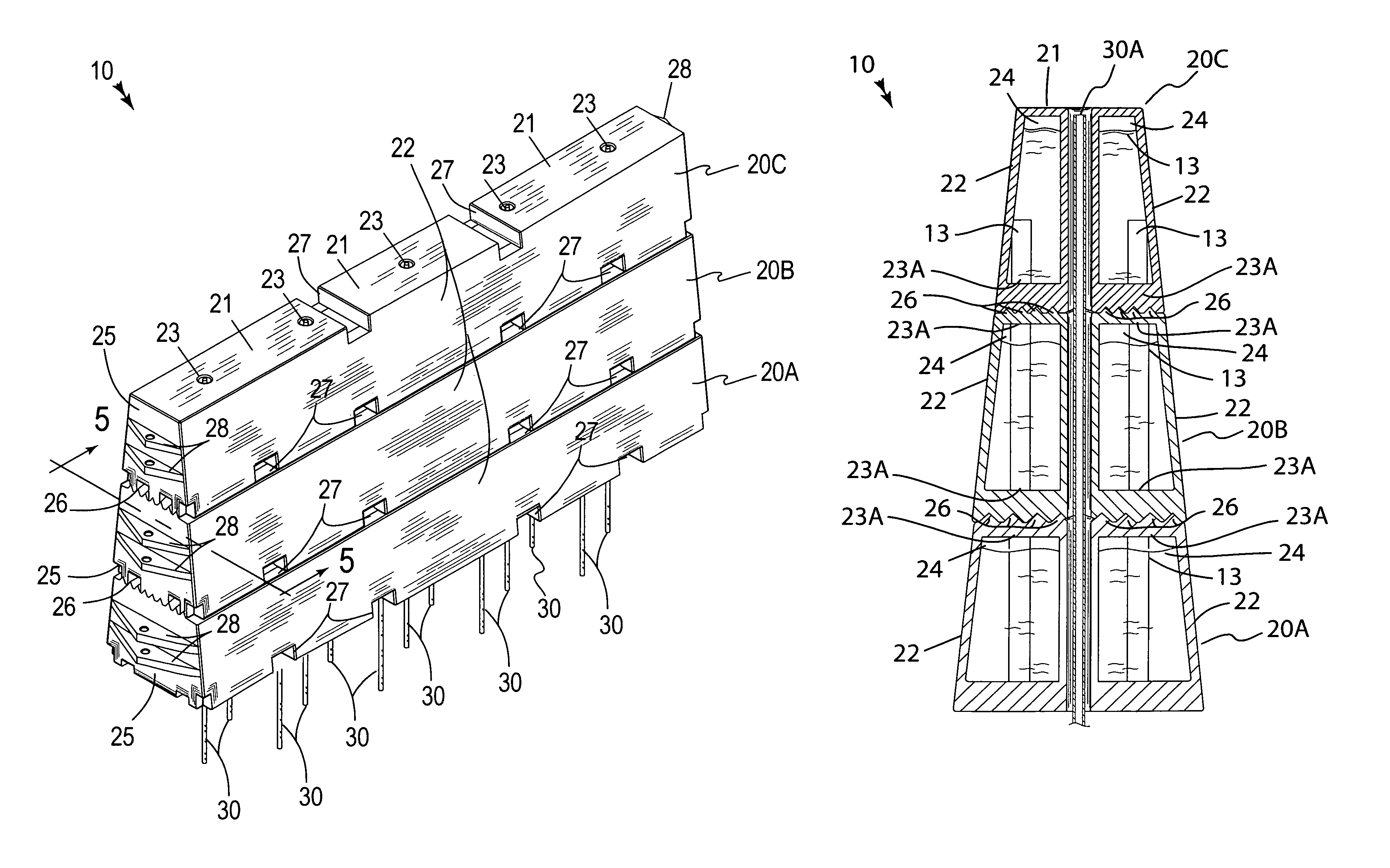
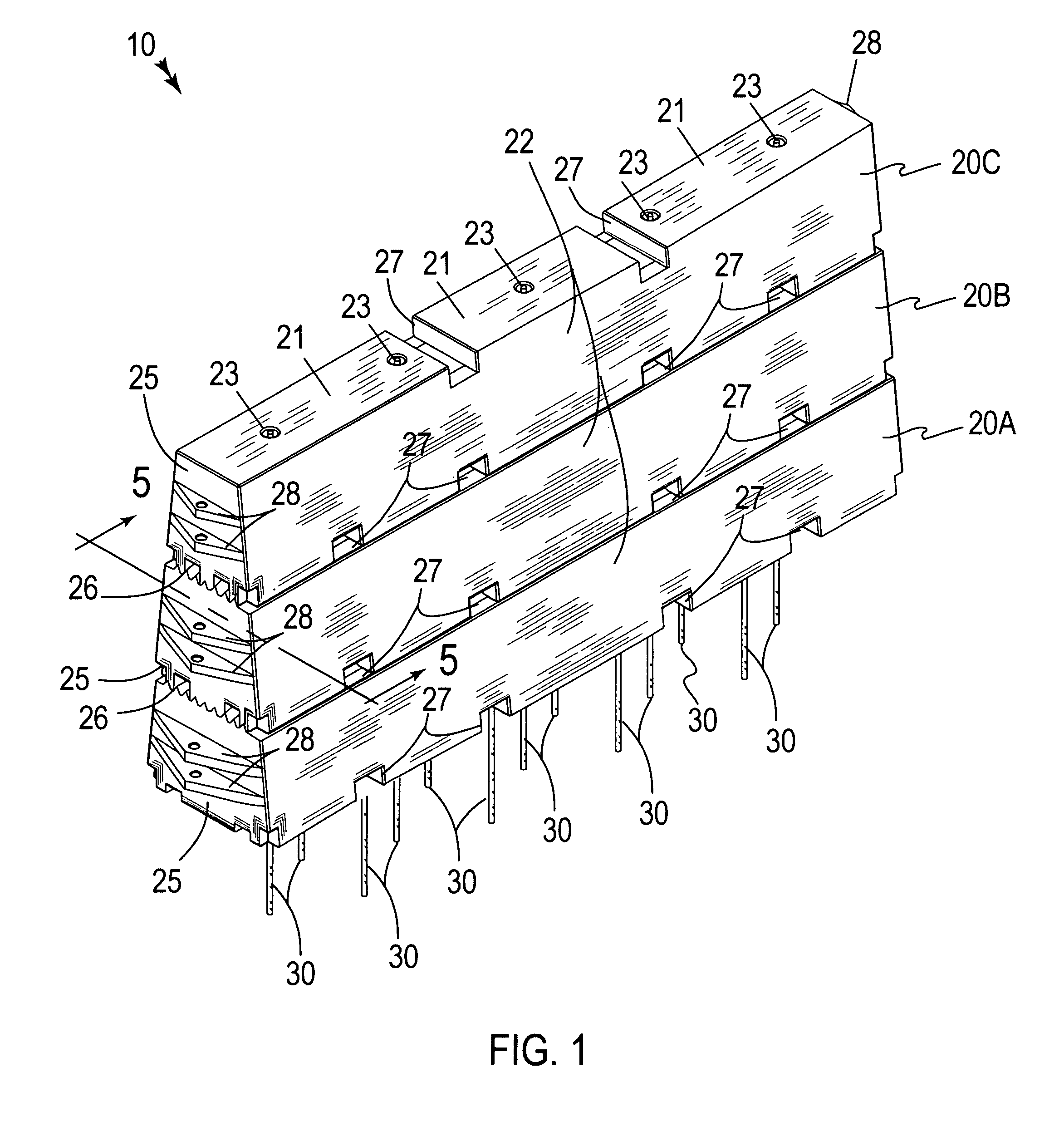
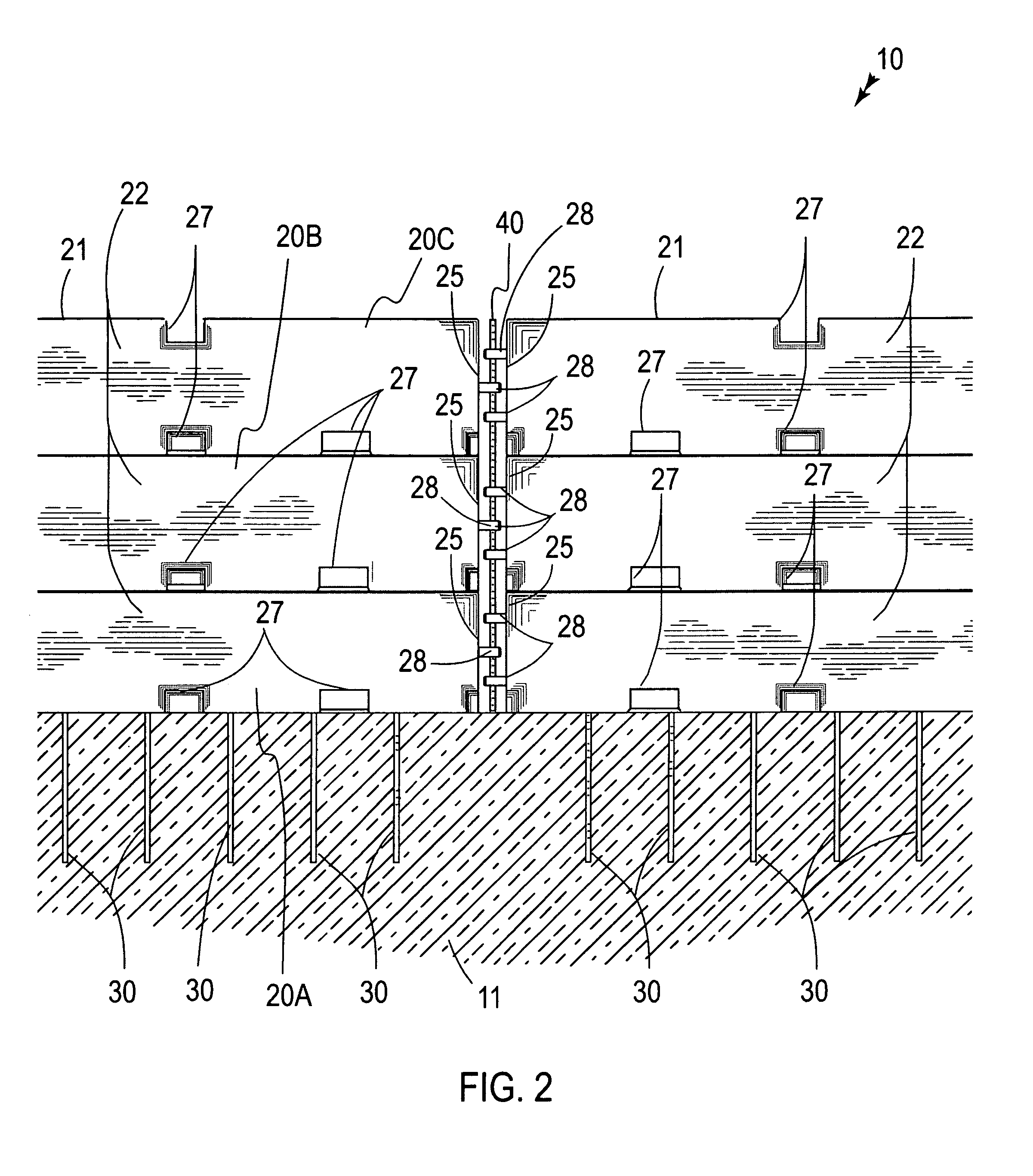
[0030]The present invention will now be described more fully hereinafter with reference to the accompanying drawings, in which a preferred embodiment of the invention is shown. This invention may, however, be embodied in many different forms and should not be construed as limited to the embodiment set forth herein. Rather, this embodiment is provided so that this application will be thorough and complete, and will fully convey the true scope of the invention to those skilled in the art. Like numbers refer to like elements throughout the figures.

[0031]The assembly of this invention is referred to generally in FIGS. 1–5 by the reference numeral 10 and is intended to provide an impact-absorbing barrier assembly. It should be understood that the assembly 10 may be used to provide a barrier in many different types of situations and should not be limited in use to only road-side construction sites.

[0032]Referring initially to FIGS. 1 through 5, the assembly 10 includes a first body 20A, a...


PUM


Abstract

A barrier assembly includes first, second and third bodies that are vertically stacked. Each body includes a top surface and side surfaces. Inlet ports are formed within the top surfaces. Isolated chambers are formed within and are equidistantly spaced from a center of each body. The bodies include opposed ends that have serrations formed therewith that are interfitted for inhibiting lateral movement of the bodies during collision. The bodies also include indentations formed therein for receiving a user's hands or a fork lift arm, and assisting the user to transport the bodies. Reinforcement rods, formed from non-corrosive material, traverse through the bodies. At least one reinforcement rod is medially seated between the isolated compartments for counterbalancing a combined weight of the bodies. A connector rod is conjoined to the bodies such that the bodies are prohibited from disengaging while experiencing an impact force.

Description

CROSS REFERENCE TO RELATED APPLICATIONS[0001]Not Applicable.STATEMENT REGARDING FEDERALLY SPONSORED RESEARCH OR DEVELOPMENT[0002]Not Applicable.REFERENCE TO A MICROFICHE APPENDIX[0003]Not Applicable.BACKGROUND OF THE INVENTION[0004]1. Technical Field[0005]This invention relates to barrier assemblies and, more particularly, to an impact-absorbing barrier assembly for absorbing and dissipating impact energy generated by a vehicle during a collision.[0006]2. Prior Art[0007]With the extensive system of highways in the United States, repair, reconstruction, and new construction are an on-going process. Work-zone safety (especially on the high-speed interstate highways) is a continuing concern. This has been illustrated by the increase in fines and penalties levied by state governments for motorists not observing reduced speed and other safety related protections in construction zones.[0008]Throughout the highway system, various signs, cones, barrels, and other guidance devices serve a va...

Claims


Application Information

Patent Timeline
Patent Type & Authority Patents(United States)
IPC IPC(8): E01F13/00
CPCE01F15/086E01F15/088
Inventor MALLINSON, CYRUS J.MALLINSON, CAROL A.
Owner MALLINSON CYRUS J
Why Eureka
Try Eureka