Machining tool, especially a milling tool

Inactive Publication Date: 2006-12-19
HARTMETALL WERKZEUGFAB PAUL HORN
View PDF10 Cites 36 Cited by
  • Summary
  • Abstract
  • Description
  • Claims
  • Application Information

AI Technical Summary

Benefits of technology

[0005]An object of the present invention is to provide an

Problems solved by technology

The properties of the material of the cutting plates this results in high production costs

Method used


Image

  • Machining tool, especially a milling tool
  • Machining tool, especially a milling tool
  • Machining tool, especially a milling tool

Examples


Embodiment Construction

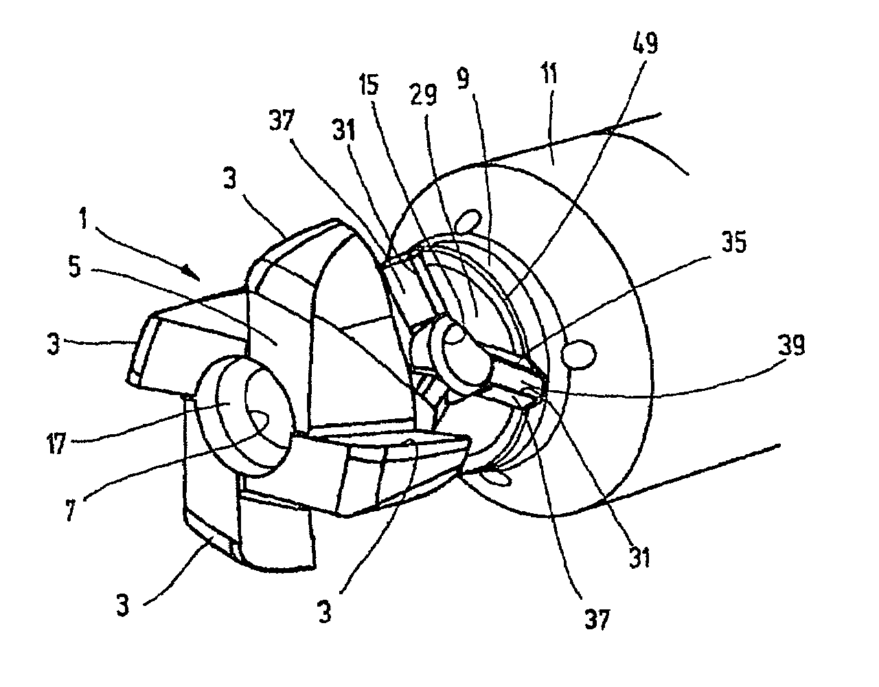
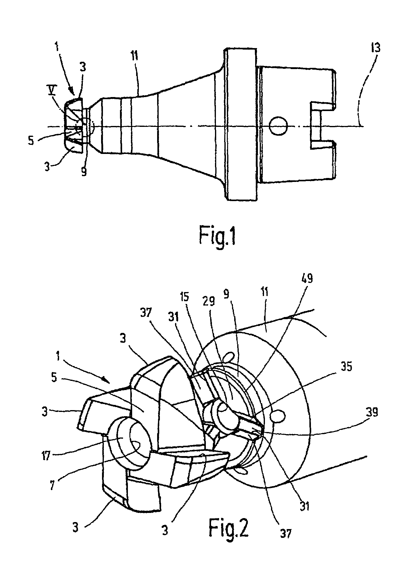
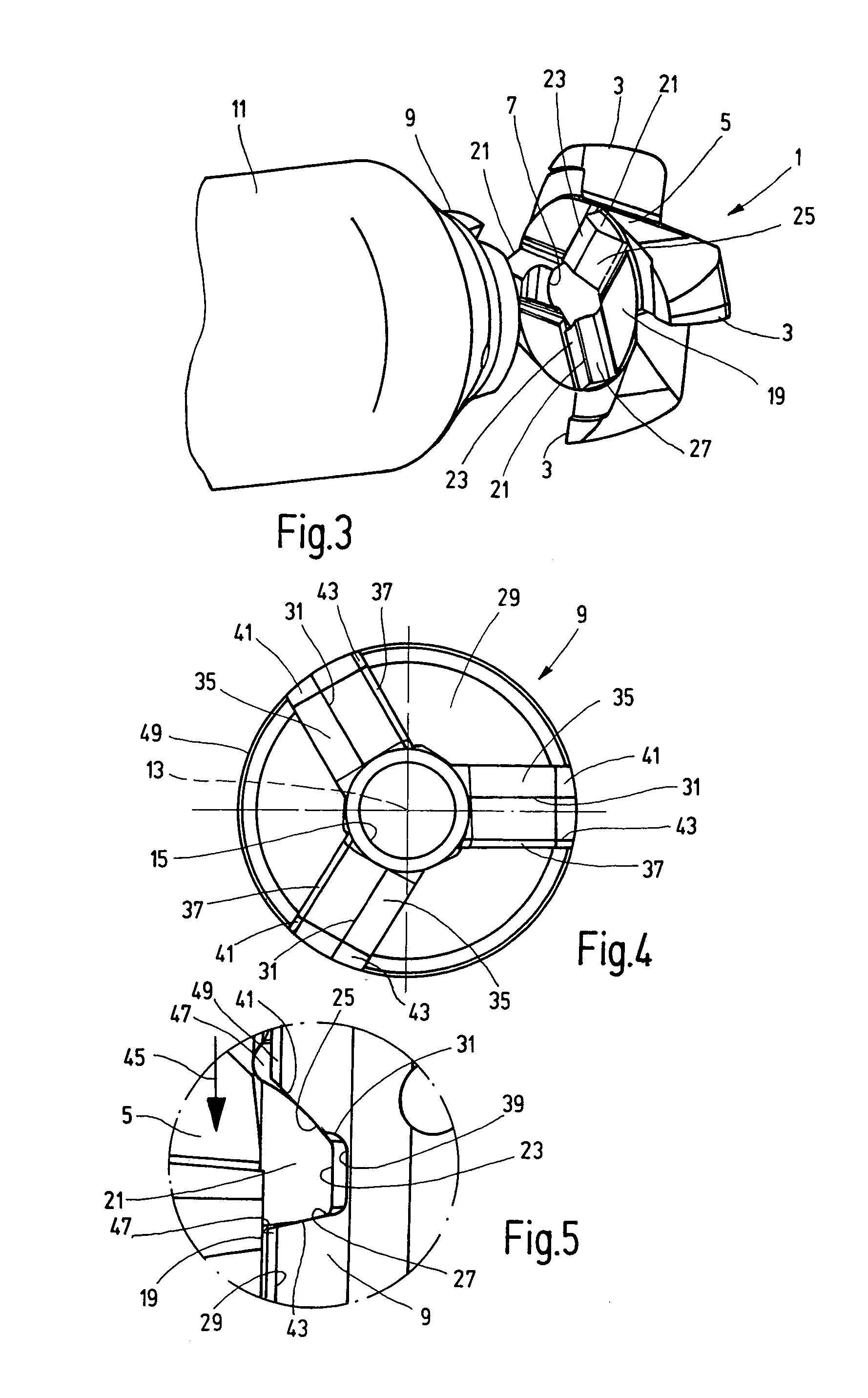
[0018]The present invention is explained with reference to an exemplary embodiment of a machine tool in the form of a milling tool having a cutting plate 1. Cutting plate 1 has four cutting edges 3 projecting radially from a central body 5 circular in outline. The body 5 has a central bore 7 for a fastening screw (not shown). The cutting plate 1 may be secured by the fastening screw on a seat 9 configured on the frontal end of a holder 11 in the form of a milling shaft having a longitudinal axis 13. The seat 9 has a threaded bore 15 coaxial with the longitudinal axis 13 for the fastening screw (not shown) for securing the cutting plate 1. This fastening screw has a cone-shaped section which, in conjunction with a tapered surface 17 situated in the vicinity of the exterior end area of the bore 7 and extending this bore 7 outward, contributes to centering of the cutting plate 1 on the seat 9 of the holder 11.

[0019]Rather than being in the form of a rotating milling tool, the embodimen...


PUM

PropertyMeasurementUnit
Angleaaaaaaaaaa
Widthaaaaaaaaaa
Distanceaaaaaaaaaa

Abstract

A machining tool, especially a milling tool, includes a shaft-like holder defining a longitudinal axis (13). A seat (9) is provided in the front face of the holder for a cutting plate that can be inserted into the holder. The cutting plate has a coupling part for mounting in the seat (9) of the holder. The coupling part has three ribs which project axially from the end surface of the cutting plate that is opposite the holder and which extend radially. The ribs are provided for engagement in complementary grooves (31) configured in the seat (9) of the holder. Their side walls (37 and 35) form driving surfaces and support surfaces, which interact for transmitting a machining torque, or as axial position safety-catch, with corresponding surfaces of the flanks of the ribs of the cutting plate. The driving surfaces and the supporting surfaces are formed by limited partial surfaces (43 and 41) of the side walls (37 and 35) of the grooves (31) whose other surfaces are retracted in relation to the partial surfaces (43 and 41) to form a spacing between the ribs and the walls of the grooves (31).

Description

FIELD OF THE INVENTION[0001]The present invention relates to a machining tool, especially a milling tool, having a shaft-like holder defining a longitudinal axis. On its frontal surface, a seat is provided for a cutting plate which may be mounted on the holder. This cutting plate has at least one cutting edge projecting radially from a central body having a bore coaxial with the longitudinal axis for a fastening screw securing the cutting plate axially on the seat of the holder, and has a coupling component for mounting on the seat of the holder having three ribs projecting axially from the end face of the body facing the holder and extending radially. The ribs are provided for engagement in complementarily configured grooves on the seat of the holder. The side walls of the grooves form driving surfaces and support surfaces which operate in conjunction with coordinated surfaces of the flanks of the ribs for transfer of operating torque or for securing the axial position.BACKGROUND O...

Claims


Application Information

Patent Timeline
IPC IPC(8): B23C7/00B23B27/00B23Q3/12B23B31/11B23C5/00B23C5/10
CPCB23B27/007B23B31/11B23C5/10B23C2210/03Y10T408/90993Y10T407/192Y10T409/30952Y10T407/1936Y10T408/95B23C2210/203
Inventor SCHAFER, HANSOETTLE, MATTHIAS
Owner HARTMETALL WERKZEUGFAB PAUL HORN
Why Eureka
Try Eureka