Image forming apparatus for reliably holding attachable units

a technology of attachable units and forming apparatuses, which is applied in the direction of electrographic process apparatus, instruments, optics, etc., can solve the problems of large size of image forming apparatuses, low printing speed, cumbersome work, etc., and achieves convenient and visual confirmation of connection condition, superior operability and safety, and stable connection condition

Active Publication Date: 2007-02-20
RICOH KK
View PDF32 Cites 28 Cited by
  • Summary
  • Abstract
  • Description
  • Claims
  • Application Information

AI Technical Summary

Benefits of technology

[0023]A first specific object of the present invention is to provide an image forming apparatus capable of reliably holding its constituent units, which are detachably attached to the image forming apparatus at predetermined positions, and superior in operability and safety when exchanging and inspecting the constituent units and in durability of the image forming apparatus.
[0024]A second specific object of the present invention is to provide an image forming apparatus that enables easy and visual confirmation of connection condition of high voltage connection terminals and connection terminals on components of the image forming apparatus, and allows the connection terminals in trouble to be fixed easily, able to obtain stable connection condition at contact points for supplying high voltages to the components.
[0025]A third specific object of the present invention is to provide an image forming apparatus having constituent units detachably attached to its main body, that is able to reliably maintain position correspondence between connection terminals of a power supply and members in the constituent units, and is superior in operability when inspecting the image forming apparatus.

Problems solved by technology

In order to form a color image in this way, usually a considerably large number of constituent components have to be used in the color image forming apparatus, and this results in a large size of the image forming apparatus compared with a monochromatic image forming apparatus, and a low printing speed, that is, the color image forming apparatus delivers a small number of the recording sheets in unit time.
However, in the above-mentioned Japanese Laid Open Patent Application No. 2002-139976, the holding member is fixed to the main body of the apparatus and it cannot be opened or closed freely.
Consequently, when taking the image forming unit or the intermediate transfer unit out from the main body of the image forming apparatus, one has to first unfasten screws, which fix the holding member with some-tools, and this work is cumbersome.
But this clearance makes the constituent units of the apparatus rattle even when the holding member is at the CLOSED position.
For this reason, even when the relative position between the photoconductor and the imaging unit is just slightly different from the expected one, shift of image transfer position may occur when transferring images of different colors to form a multi-color image, and this causes low quality images involving color deviation or image transfer position shift.
For example, when a metal plate is used for the holding member, while the strength of the holding member is improved, weight of the holding member also increases, and the image forming apparatus may topple over when the holding member is opened.
However, reducing the room in the main body makes usage of the detachable connectors difficult.
However, since the high voltage connection terminals and the connection terminals on the components of the image forming apparatus are connected in the depths of the main body, it is difficult to confirm whether the connection condition of them is good or not, and particularly, even when the high voltage connection terminals in the depths of the main body have a problem, for example, the terminals are bent somehow, it is difficult to find out about the problem.
Moreover, even if the defects of the connection terminals are confirmed, in order to repair the terminals, one has to remove a cover on the inner side of the main body, and one cannot fix the problem easily.

Method used


Image

  • Image forming apparatus for reliably holding attachable units
  • Image forming apparatus for reliably holding attachable units
  • Image forming apparatus for reliably holding attachable units

Examples


first embodiment

[0133

[0134]In the present embodiment, a color printer having a tandem engine configuration and capable of full-color printing is used as an example. It is apparent that the image forming apparatus of the present embodiment is not limited to the color printer illustrated; it may also be a copier, a facsimile machine or others.

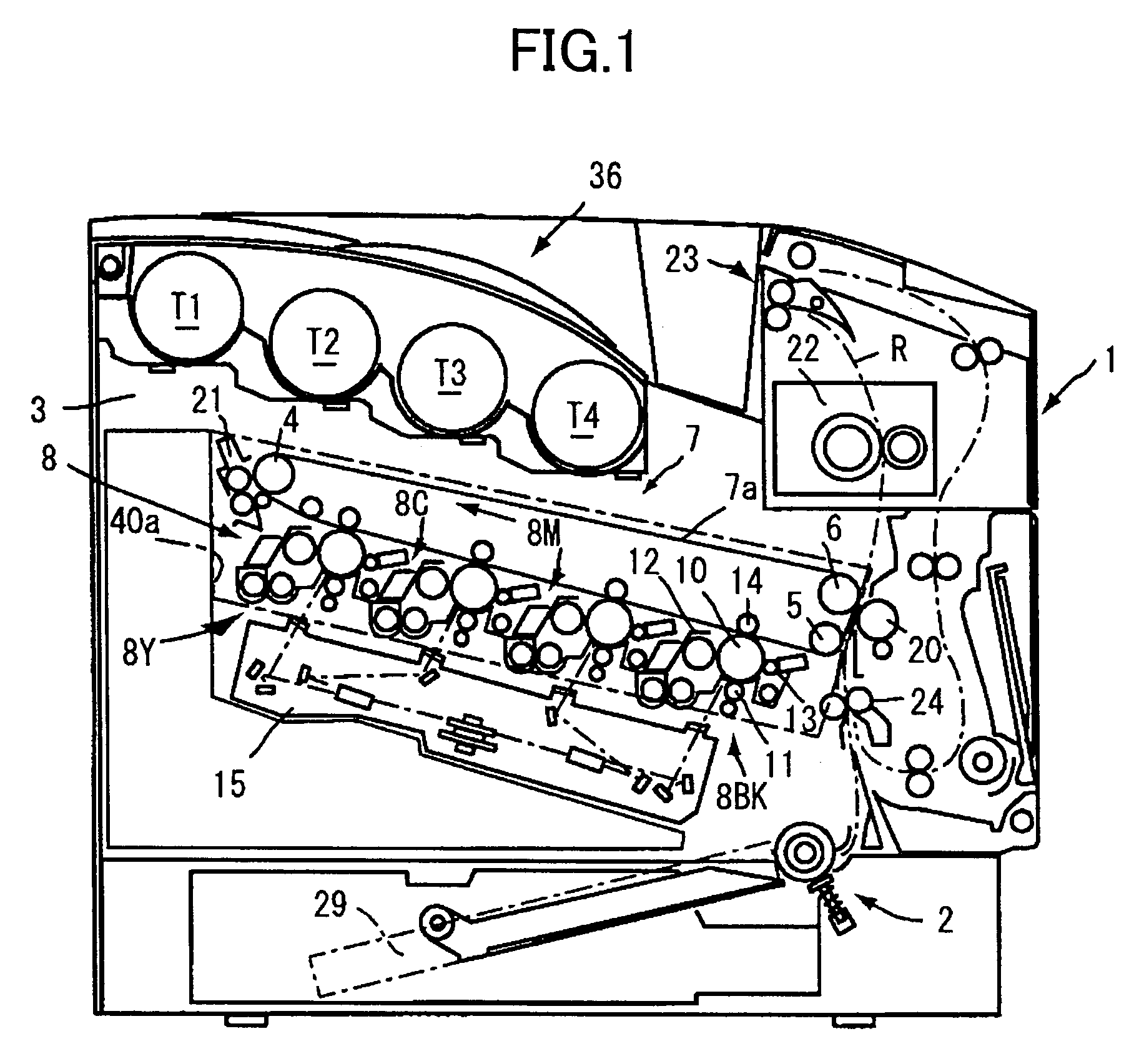
[0135]FIG. 1 is a front view showing a schematic configuration of a color printer according to the present embodiment.

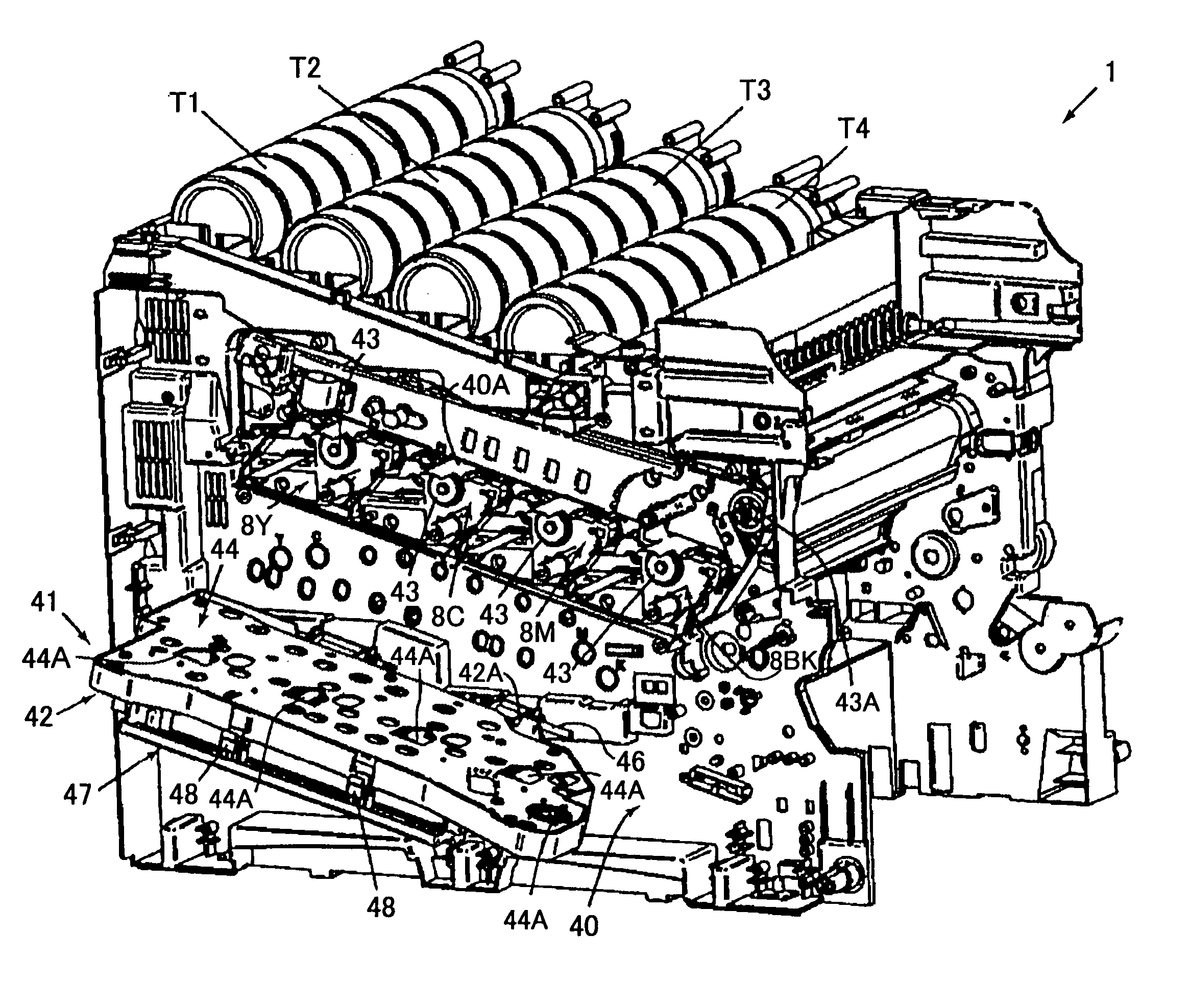
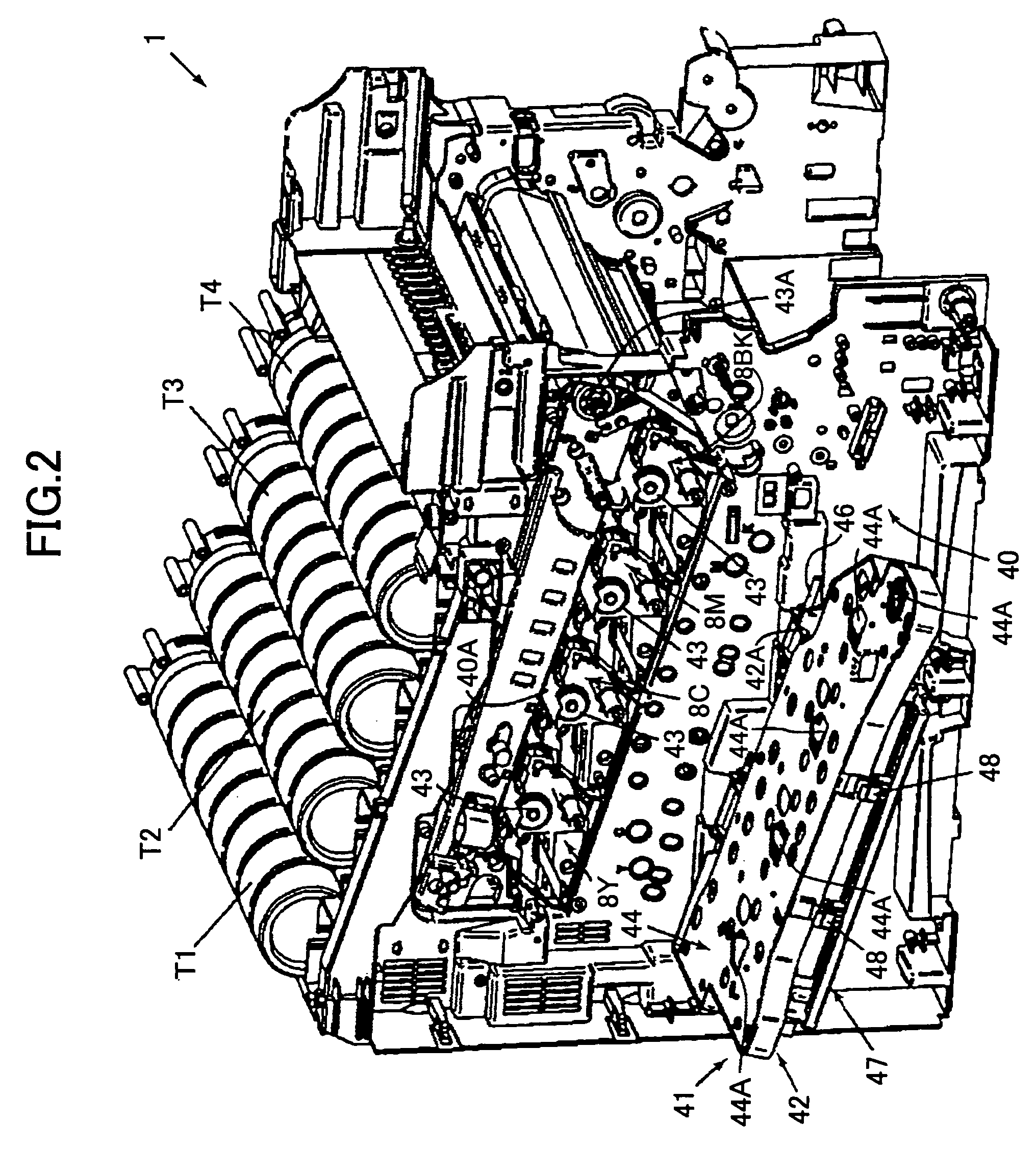
[0136]The color printer in FIG. 1 includes a main body 1, a feeding section 2 in the lower portion of the main body 1 for accommodating paper or other recording sheets 29, and an imaging forming section 3 in the upper portion of the main body 1.

[0137]The imaging forming section 3 includes an image generation part 8 having a number of image forming devices, specifically, four image forming units 8Y, 8C, 8M, 8BK, each including a photo conductor 10 on which images are formed, rollers 4, 5, 6, an intermediate transfer unit 7 having an intermediate t...

second embodiment

[0339

[0340]In the present embodiment, it is assumed that the image forming apparatus is a color printer having a tandem engine configuration and capable of full-color printing.

[0341]FIG. 33 is a front view showing a schematic inner configuration of a color printer 201 according to the present embodiment.

[0342]The color printer 201 in FIG. 33 includes a main body 202, an imaging forming section 203, an optical writing section 204, a feeding section 205, and a fusing section 206.

[0343]The imaging forming section 203 includes four image forming units 207Y, 207C, 207M, 207K, and an intermediate transfer unit 208 and a secondary transfer roller 220 are arranged above the imaging forming section 203. The secondary transfer roller 220 is supplied with electric power. Below, such members are referred to as component members of the image forming apparatus.

[0344]The image forming units 207Y, 207C, 207M, 207K have the same structure, but toners (developing agents) held in the developing device...

third embodiment

[0451

[0452]FIG. 51 is a cross-sectional view of a principal portion of the power feeding panel 253 according to the third embodiment. In the following description, the same reference numbers are used for the same components as those in the previous embodiment, and overlapping explanations are omitted.

[0453]In this embodiment, the power feeding panel 253 includes a power feeding structure 2101, which is different from the power feeding structure 260 in the second embodiment.

[0454]In the power feeding structure 2101, the conductive pin 261 is slidable in the direction along its axial center, and when the power feeding panel 253 is turned to the CLOSED position, the front end of the conductive pin 261 is in contact with the connection terminal 268 of a component member, such as, the developing roller 211, the charging roller 210, which are installed inside the main body 202.

[0455]The conductive spring 269 is connected to the conductive pin 261 to push the conductive pin 261 to contact ...


PUM


Abstract

An image forming apparatus is disclosed that holds its detachably attached constituent units at predetermined positions for operations, and releases the hold when exchanging and inspecting the constituent units. The image forming apparatus includes a main body having an opened portion on one side, one or more devices detachably attached to the main body through the opened portion, and a holding unit that is capable of being opened and closed relative to the opened portion. The holding unit is engaged with the devices and holds the devices at the predetermined positions when the holding unit is closed relative to the opened portion. A fixing unit arranged on the holding unit fixes the holding unit when the holding unit is closed.

Description

BACKGROUND OF THE INVENTION[0001]1. Field of the Invention[0002]The present invention relates to an image forming apparatus, such as a color printer, a color copier, a color fax machine, or a combination of them.[0003]2. Description of the Related Art[0004]It is well known that an electrophotographic image forming apparatus forms color images on recording materials such as paper or films (below, they are referred to as “recording sheet”) by using toners (developing agents) usually having four colors. In order to form a color image in this way, usually a considerably large number of constituent components have to be used in the color image forming apparatus, and this results in a large size of the image forming apparatus compared with a monochromatic image forming apparatus, and a low printing speed, that is, the color image forming apparatus delivers a small number of the recording sheets in unit time.[0005]Along with wide-spread use of personal computers, image forming apparatuses ...

Claims


Application Information

Patent Timeline
Patent Type & Authority Patents(United States)
IPC IPC(8): G03G15/00G03G21/16
CPCG03G21/16G03G2221/1606G03G21/1633
Inventor KUMA, KAZUOSANOGUCHI, YUUSUKEISHII, HIROSHIKIKURA, MAKOTOFUKUCHI, YUTAKASUZUKI, KAZUKI
Owner RICOH KK
Why Eureka
Try Eureka