Projectile

a projectile and projectile body technology, applied in the field of projectiles, can solve the problems of easy damage to the programmable device, delicate and easily damaged elements, etc., and achieve the effects of short processing time, increased target surface, and cost-intensiv

Inactive Publication Date: 2007-04-03
OERLIKON CONTRAVES PYROTEC
View PDF21 Cites 0 Cited by
  • Summary
  • Abstract
  • Description
  • Claims
  • Application Information

AI Technical Summary

Benefits of technology

The solution reduces non-effective mass, protects sensitive components, and enhances velocity and target effectivity by distributing explosives towards the front, enabling flexible manufacturing and improved performance in air burst applications.

Problems solved by technology

Therefore the programmable device has delicate and easily damaged elements, which must be well protected so that they can withstand the large forces caused by the acceleration.

Method used


Image

  • Projectile
  • Projectile

Examples


Embodiment Construction

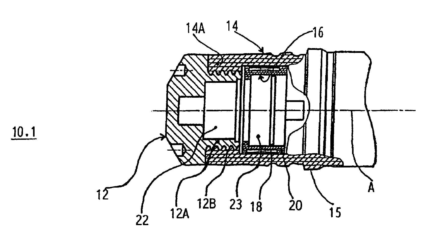
[0028]The projectile 10.1 with the longitudinal projectile axis A represented in FIG. 1 has a projectile base 12 made of a suitable metal and a casing 14 which is made of a suitable plastic material, at least in the rear area, but preferably as a whole. The casing 14 has been produced by means of a pressure or injection molding process, but could alternatively also be shaped by a machining process. The connection of the casing 14 with the projectile base 12 can take place simultaneously with the production of the casing. To provide a secure connection between the projectile base and the casing 14, the projectile base 12 has grooves 12b on the exterior of its base area 12A, which project forward, and is essentially hollow-cylindrical. The material of the casing 14 has been injected around the grooves 12b, so that the forward projecting base area 12A is connected with a casing area 14A projecting toward the rear.

[0029]It is also possible to fasten the projectile base 12 and the casing...


PUM


Abstract

A projectile, having a casing, a projectile base, which closes off the casing at the rear, a receiver coil for receiving electromagnetic signals, an energy source, brought into contact with the receiver coil, and a logic module. The casing is made of a plastic material, at least in the area of the rear.

Description

FIELD OF THE INVENTION[0001]This patent application is a divisional application of U.S. patent application Ser. No. 10 / 093,262, filed on Mar. 6, 2002, now U.S. Pat. No. 6,874,402 which claims priority from Swiss Patent Application No. 2001 / 0472 / 01, filed on Mar. 14, 2001, the disclosures of which are herein incorporated by reference in their entirety.[0002]The invention relates to a projectile of the type of ABM (air burst ammunition).BACKGROUND OF THE INVENTION[0003]Projectiles of this type are intended to disintegrate in flight, or to detonate, and are also called “air bursting munitions”, abbreviated as ABM. Projectiles which detonate in flight have a timed fuse, revolution fuse or proximity fuse. The location or the time of detonation should be selectable, or adjustable. With more recent projectiles the setting of the time of detonation, or the length of the fuse, is no longer manually performed prior to loading, but automatically, either during feeding, or in the cartridge stor...

Claims


Application Information

Patent Timeline
Patent Type & AuthorityPatents(United States)
IPC IPC(8): F42C13/00F42B3/11F42B8/14F42B12/22F42B12/76F42B30/00F42C19/02
CPCF42B12/76F42B30/006F42C19/02
InventorETTMULLER, PETER
OwnerOERLIKON CONTRAVES PYROTEC