
Aliasing reduction using complex-exponential modulated filterbanks
a filterbank and complex technology, applied in pulse manipulation, pulse technique, instruments, etc., can solve the problem of severe aliasing artifacts in the output signal, and achieve the effect of significantly reducing the effects of subband signal modifications
Patent Information
- Authority / Receiving Office
- US · United States
- Current Assignee / Owner
- Publication Date
- 2007-07-10
Smart Images
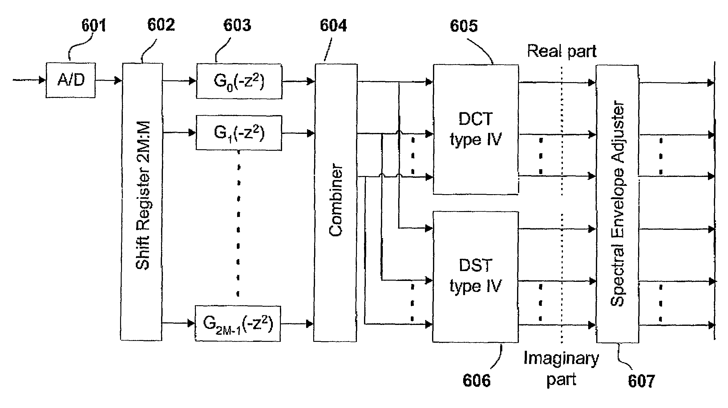
Figure 1 
Figure 2 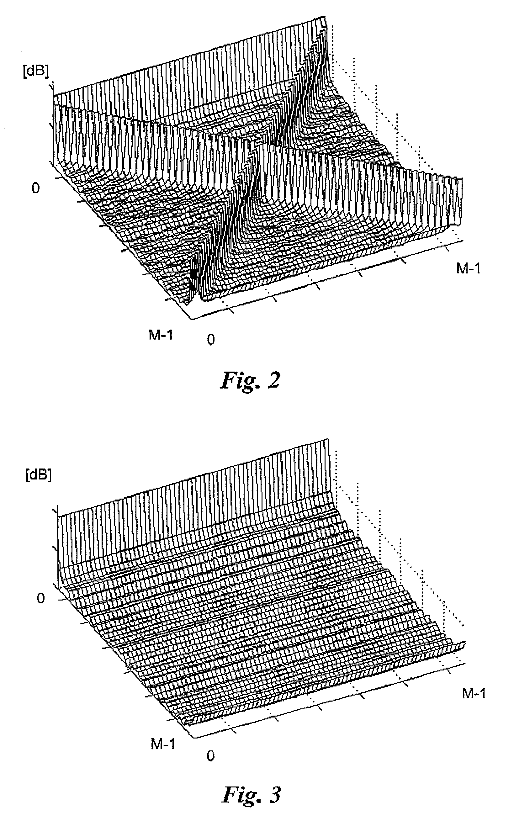
Figure 3
Abstract
Description
TECHNICAL FIELD
[0001] The present invention relates to the area of subsampled digital filterbanks and provides a new method and apparatus for substantial reduction of impairments emerging from modifications, for example quantization or attenuation, of the spectral coefficients or subband signals of digital filterbanks. The invention is applicable to digital equalizers [“An Efficient 20 Band Digital Audio Equalizer” A. J. S. Ferreira, J. M. N. Viera, AES preprint, 98th Convention 1995 February 25–28 Paris, N.Y., USA], adaptive filters [Adaptive Filtering in Subbands with Critical Sampling: Analysis, Experiments, and Application to Acoustic Echo Cancellation” A. Gilloire, M. Vetterli, IEEE Transactions on Signal Processing, vol. 40, no. 8, August, 1992], multiband companders, and to audio coding systems using high frequency reconstruction (HFR), where a digital filterbank is used for the adaptive adjustment of the spectral envelope, such as the Spectral Band Replication (SBR) system [W...
Examples
Embodiment Construction
[0020]It should be understood that the present invention is applicable on a range of implementations that incorporates digital filterbanks other than those explicitly mentioned in this patent.
Digital Filterbanks
[0021]A digital filter bank is a collection of two or more parallel digital filters that share a common input or a common output [“Multirate Systems and Filter Banks” P. P. Vaidyanathan Prentice Hall: Englewood Cliffs, N.J., 1993]. When sharing a common input the filter bank is called an analysis bank. The analysis bank splits the incoming signal into M separate signals called subband signals. The analysis filters are denoted Hk(z, where k=0 . . . M−1. The filter bank is critically sampled (or maximally decimated) when the subband signals are decimated by a factor M. The total number of subband samples per unit time is then the same as the number of samples per unit time for the input signal. The synthesis bank combines these subband signals into a common output signal. The s...