Organic electroluminescent element, material for positive hole injecting layer, and organic electroluminescent display

a technology of organic electroluminescent elements and positive hole injection, which is applied in the direction of discharge tube luminescnet screens, natural mineral layered products, other domestic articles, etc., can solve the problems of insufficient diode properties, and insufficient effect to increase the amount of injected positive holes. , to achieve the effect of superior luminance, low voltage, and sufficient luminan

Inactive Publication Date: 2007-07-31
UDC IRELAND
View PDF21 Cites 1 Cited by
  • Summary
  • Abstract
  • Description
  • Claims
  • Application Information

AI Technical Summary

Benefits of technology

[0010]Inventors of the present invention have investigated vigorously in order to solve the problems described above, and have developed the present invention. Namely, the present invention is based on the following experiences or discoveries: when a positive hole injecting layer containing a perfluoropolyether (PFPE) compound is formed on a positive electrode, the amount of injected positive holes can be further increased, the organic EL element can actuate at lower voltages, leak currents hardly flow for minus or negative voltages thus perform a appropriate diode property, and the occurrences of crosstalk can be reduced effectively.
[0011]The material for the positive hole injecting layer contains a perfluoropolyether compound. Accordingly, the positive hole injecting layer that is formed by the material for the positive hole injecting layer can provide higher amount of injected positive holes compared to conventional positive hole injecting layers formed by the other materials, and can exhibit proper diode properties with lower leak current at negative biases.
[0012]The organic EL element according to the present invention comprises an organic thin film layer that contains the positive hole injecting layer between a positive electrode and a negative electrode; the positive hole injecting layer comprises the perfluoropolyether compound. Accordingly, the organic EL element can represent appropriate adhesive ability since the positive hole injecting layer exhibits proper wettability against the adjacent positive electrode and the positive hole transporting layer thus hardly occurs the delamination between layers; in addition, the organic EL element can provide higher luminance with lower voltages since the amount of injected positive holes at the positive hole injecting layer is higher than the amounts of injected positive holes in the prior art.
[0013]Moreover, splintery rough surface that appears typically on the surface of positive electrodes may be smoothened by the positive hole injecting layer, thus the leak current is lowered at negative biases and proper diode properties can appear, and electrical short can be effectively relaxed. As a result, the organic EL display formed using the organic EL element can represent lower occurrences of cross talk.
[0016]Since such crosstalk may be inhibited efficiently in the organic EL element according to the present invention, sufficient level of luminance may be obtained with lower voltages, and superior luminance and high reliability may be provided.
[0017]The organic EL display according to the present invention comprises the organic EL element according to the present invention. Accordingly, such crosstalk may be inhibited efficiently, sufficient level of luminance may be obtained with lower voltages, and superior luminance and high reliability may be provided.

Problems solved by technology

However, organic EL elements that are manufactured by forming a light emitting layer on a positive electrode formed of ITO etc. suffer from insufficient amount of injected positive holes and non-actuating at lower voltages.
However, these proposals suffer from some problems still in that the effect is not sufficient yet to increase the amount of injected positive holes; leak currents flow when negative voltages are applied; diode properties are not sufficient; reliability is not sufficient; and wettability is not sufficient with the adjacent layers.

Method used


Image

  • Organic electroluminescent element, material for positive hole injecting layer, and organic electroluminescent display
  • Organic electroluminescent element, material for positive hole injecting layer, and organic electroluminescent display
  • Organic electroluminescent element, material for positive hole injecting layer, and organic electroluminescent display

Examples


example 1

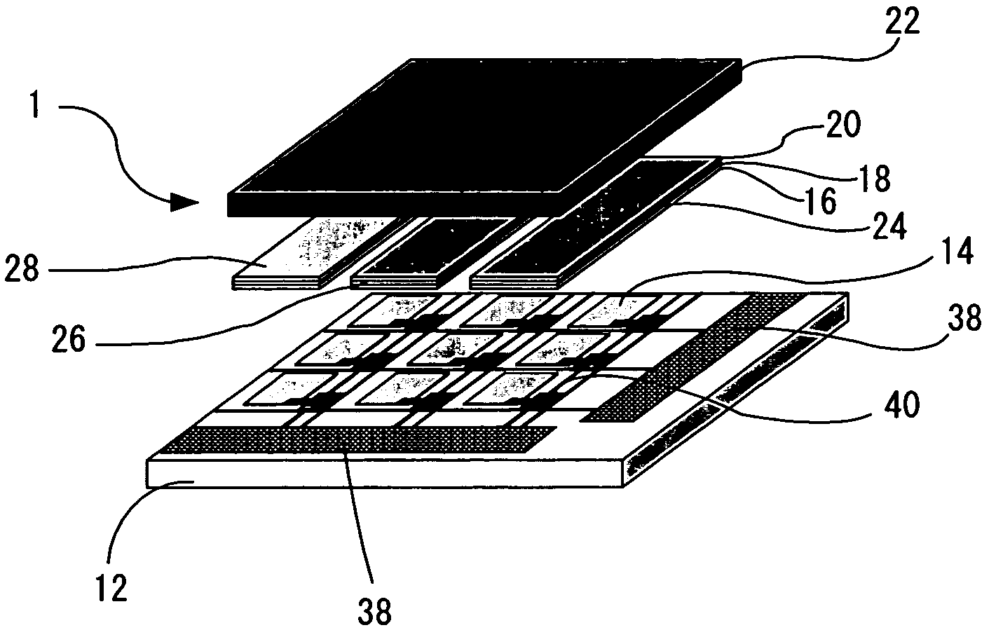
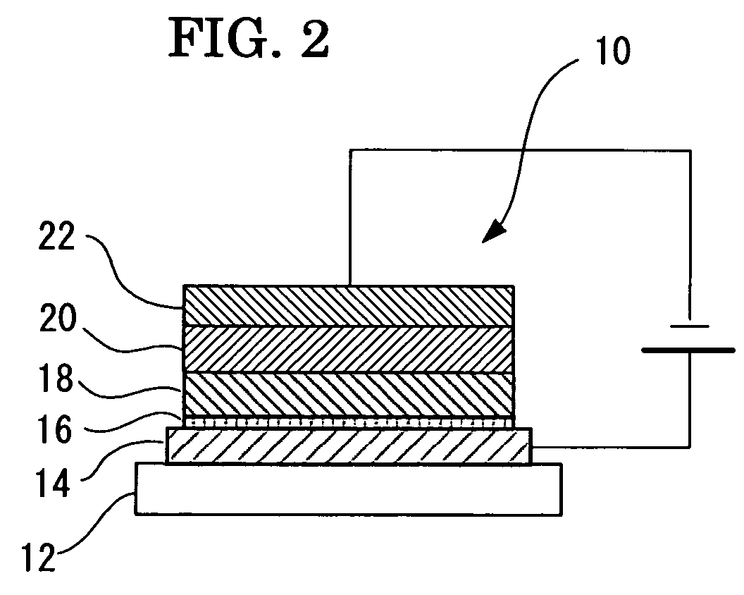
[0207]Manufacture of Organic EL Element

[0208]A glass substrate equipped with an ITO electrode was prepared as a positive electrode. The ITO electrode was subjected to ultrasonic cleaning in water, acetone, and isopropyl alcohol, then was subjected to UV ozone treatment.

[0209]An amine salt compound of perfluoropolyether (PFPE) expressed by the formula below (weight-averaged molecular weight: 4000, by SONY) was employed as a material for positive hole injecting layer. The amine salt compound was dissolved into a solvent (FC77, by 3M) to prepare a solution of coating liquid for positive hole transporting layer that contained 0.023% by mass of the amine salt compound. Then the positive electrode was dipped in the solution of coating liquid and pulled up in a raise rate of 100 mm / min thereby to form a positive hole injecting layer of 0.8 nm thick on the ITO.

R1—(CF2—O)x(C2F4—O)y—R2

[0210]in the above formula, x=20 or less, y=20 or less, y / x=1; R1 and R2 are represented by the following fo...


PUM

PropertyMeasurementUnit
thicknessaaaaaaaaaa
ionization potentialaaaaaaaaaa
voltagesaaaaaaaaaa

Abstract

The present invention relates to highly reliable organic EL elements that can provide higher luminance with lower voltage and exhibit lower leak current at negative biases and appropriate diode properties. The organic EL element comprises a positive hole injecting layer, and a perfluoropolyether compound is incorporated into the positive hole injecting layer. Preferably, the perfluoropolyether compound is expressed by formula (1) or (2),R1—Rf—R2  formula (1)Rf—R3  formula (2)in which, R1, R2, and R3 represents one of a hydrogen atom, a fluorine atom, and a substituted group; Rf represents the perfluoropolyether skeleton expressed by the formula (3),in which, R4 and R5 represent general formula —CpF2p+1; n, m, x, and y are each an integer.

Description

CROSS-REFERENCE TO RELATED APPLICATIONS[0001]This is a continuation of Application PCT / JP2003 / 000887, filed on Jan. 30, 2003.BACKGROUND OF THE INVENTION[0002]1. Field of the Invention[0003]The present invention relates to positive hole injecting materials that can increase the amount of injected positive holes; highly reliable organic electroluminescent (EL) elements that can provide higher luminance with lower voltage and exhibit lower leak currents at negative biases; and higher performance organic EL displays that utilize the organic EL elements.[0004]2. Description of the Related Art[0005]Organic EL elements have features such as self-luminousness and rapid response, and are expected to apply to flat panel displays. Such organic EL elements are attracting worldwide interests in terms of larger area elements that are capable of emitting light at lower voltages such as 10 V or less, since two-layer type or laminated type organic EL elements were announced that were prepared by lam...

Claims


Application Information

Patent Timeline
Patent Type & Authority Patents(United States)
IPC IPC(8): H01L51/50H01L21/312H01L51/00H01L51/30H05B33/22
CPCH01L51/004H05B33/22H01L21/3127H01L51/0034H01L51/0035H01L51/0036H01L51/0038H01L51/0039H01L51/0041H01L51/0042H01L51/005H01L51/0052H01L51/0059H01L51/0062H01L51/007H01L51/0081H01L51/5088Y10S428/917Y10T428/31515H10K85/10H10K85/141H10K85/114H10K85/143H10K85/146H10K85/115H10K85/111H10K85/60H10K85/113H10K85/649H10K85/6565H10K85/631H10K85/615H10K85/324H10K50/17H01L21/0212
Inventor ITAI, YUICHIROIIDA, TAKASHIKODAMA, JUN
Owner UDC IRELAND
Why Eureka
Try Eureka