

Padlock
a technology of padlocks and latches, applied in the field of padlocks, can solve problems such as dangerous current flow through the body of the user of the lock, and achieve the effect of improving the mechanical stability of the latches and better guidance on insertion
- Summary
- Abstract
- Description
- Claims
- Application Information
AI Technical Summary
Benefits of technology
Problems solved by technology
Method used
Image

Examples
Embodiment Construction
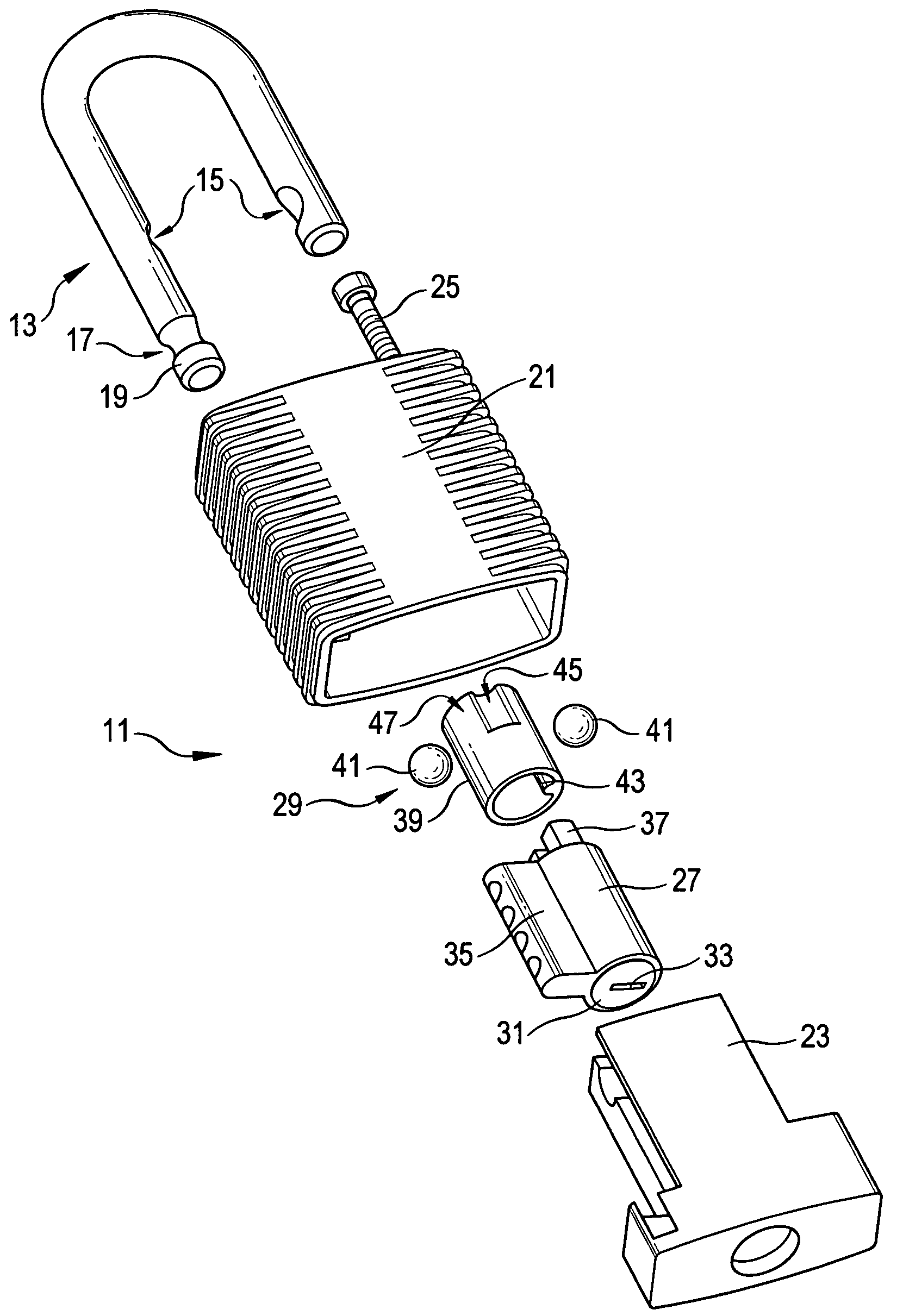
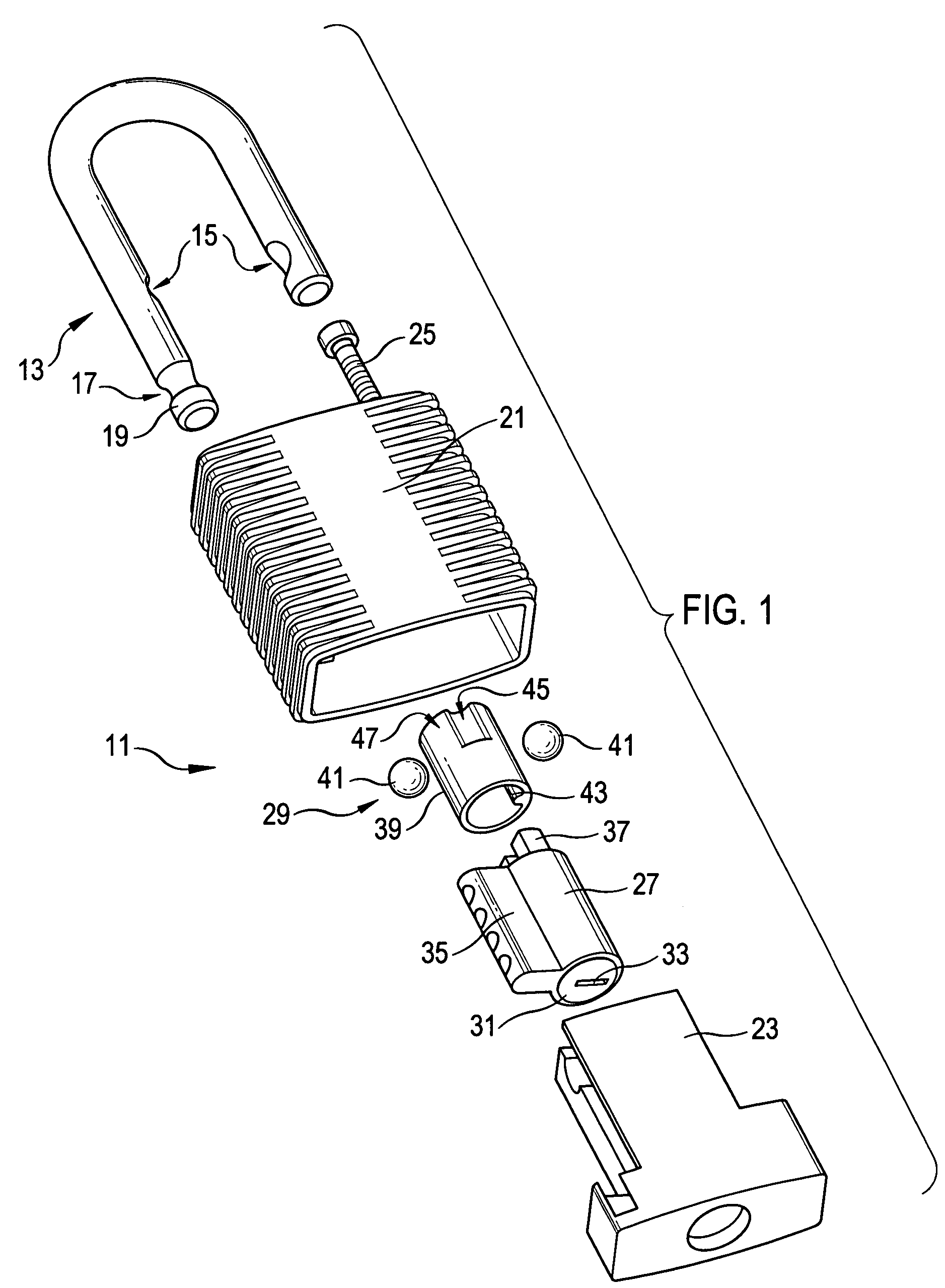
[0031]FIG. 1 shows the basic design of a padlock in accordance with the invention. It has a lock body 11 and a lock hoop 13. The hoop 13 has a U shape with one shorter limb and one longer limb. An inwardly directed latching recess 15 is formed at both limbs. Furthermore, a ring groove 17 with an abutment head 19 adjoining it is provided at the free end of the longer limb.
[0032]The lock body 11 has an outer housing part 21 and an inner housing part 23. These each consist completely, or at least at the outer side, of an electrically insulating plastic, for example of PBT (polybutylene terephthalate). The inner housing part 23 can be pushed into the outer housing part 21 and fixed to the outer housing part 21 by means of a securing screw 25, as will be explained in the following. The outer housing part 21 and the inner housing part 23 accommodate a lock cylinder 27 and a latching mechanism 29.
[0033]The lock cylinder 27 has, in a manner known per se, a cylinder core 31 with a keyway 33....
PUM
 Abstract
Description
Claims
Application Information