Methods for detecting compression wood in lumber

a technology of compression wood and lumber, applied in the direction of color/spectral property measurement, measurement device, instruments, etc., can solve the problems of inability to apply real-time, inconvenient to real-time industrial applications, and inability to use microscopy methods

Active Publication Date: 2007-12-04
WEYERHAEUSER NR CO
View PDF3 Cites 8 Cited by
  • Summary
  • Abstract
  • Description
  • Claims
  • Application Information

AI Technical Summary

Problems solved by technology

Microscopy methods have the disadvantage that they cannot be applied in real time, in an industrial setting with lumber moving at planar speeds (

Method used


Image

  • Methods for detecting compression wood in lumber
  • Methods for detecting compression wood in lumber
  • Methods for detecting compression wood in lumber

Examples


Embodiment Construction

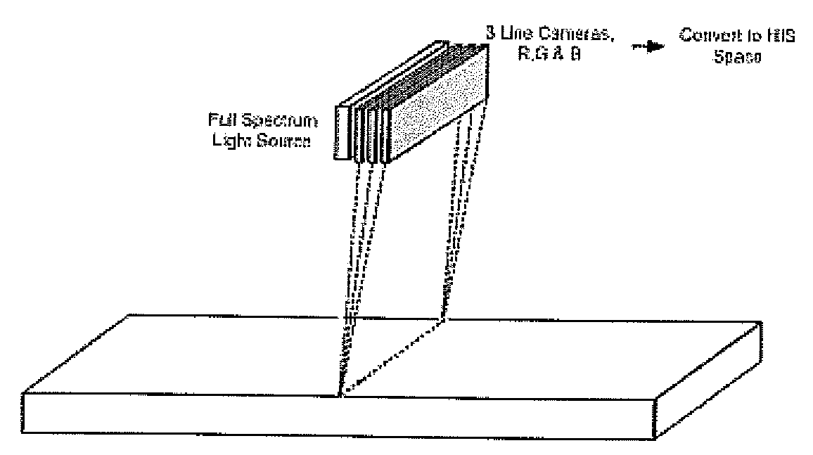
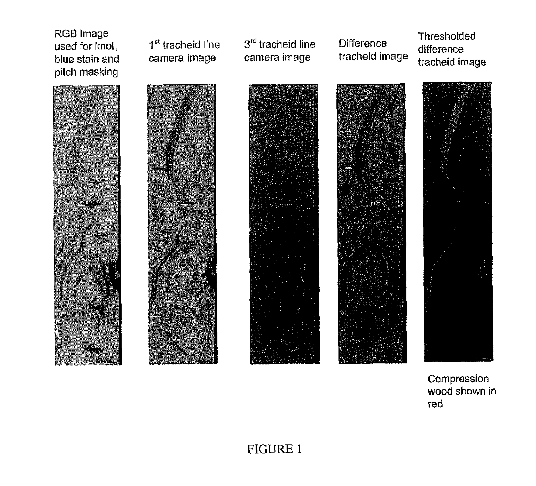
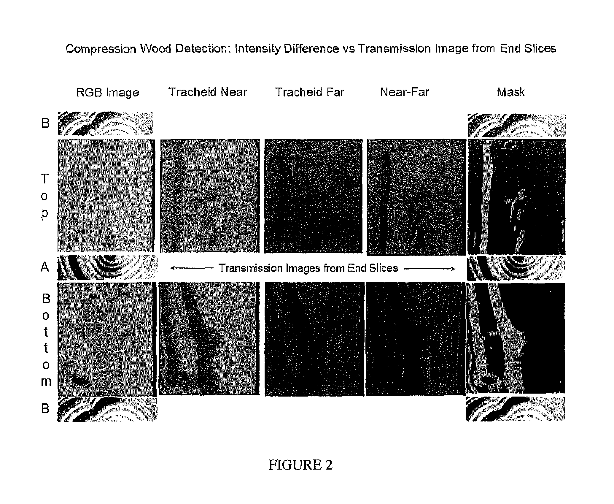
[0014]The present invention generally relates to detection of compression wood, blue stain, or pitch in a wood sample. A light beam is projected towards the wood sample. The light beam may be in the form of a laser line. In an embodiment, the light beam may be in the form of individual spots of light. Line or area cameras acquire images of light that is reflected from the wood sample. Based on the intensity of the reflected light at one or more locations on the wood sample, compression wood, blue stain, or pitch may be detected.

Compression Wood Detection in Lumber

[0015]In an embodiment, the compression wood detection system is directed to transporting lumber longitudinally past an image acquisition system. The imaging system consists of laser lines projected across the width of the board faces (top and bottom) and either line cameras or area cameras to record the intensity of diffusely reflected light on either side of the laser line. The method can be extended to include the board ...


PUM


Abstract

Methods are provided for detecting compression wood, blue stain, or pitch in lumber. A light beam is projected towards the wood sample. Line or area cameras acquire images of light that is reflected from the wood sample. Based on the intensity of the reflected light at one or more locations on the wood sample, compression wood, blue stain, or pitch may be detected.

Description

FIELD OF THE INVENTION[0001]This invention relates generally to methods for detecting blue stain in lumber.BACKGROUND OF THE INVENTION[0002]It is generally known to identify compression wood, blue stain, and pitch in a wood sample. With respect to detecting compression wood, known methods would include optical and scanning electron microscopy to identify compression wood areas. In normal wood, the S2 layer (the thickest cell wall layer comprised of ordered microfibrils nearly parallel to the long axis of the cell) is continuous and characterized by low microfibril angles. In compression wood the S2 layer is fractured and is characterized by high microfibril angles. Microscopy methods have the disadvantage that they cannot be applied in real time, in an industrial setting with lumber moving at planar speeds (up to 2500 fpm). The other primary method used to identify compression wood consists of transmission imaging of thin cross sections of boards. In this method, thin cross sections...

Claims


Application Information

Patent Timeline
IPC IPC(8): G01N21/00G01N21/31
CPCG01N21/8986G01N21/25
Inventor TAYLOR, THOMAS J.
Owner WEYERHAEUSER NR CO
Why Eureka
Try Eureka