Display unit with touch panel

a display unit and touch panel technology, applied in the direction of identification means, instruments, machine supports, etc., can solve the problems of requiring some time for recognition and necessary to stop the function

Active Publication Date: 2007-12-25
MAXELL HLDG LTD
View PDF11 Cites 211 Cited by
  • Summary
  • Abstract
  • Description
  • Claims
  • Application Information

AI Technical Summary

Benefits of technology

[0010]An object of the present invention is to provide a display unit free from the problems and capable of recognizing easily that the fingertip has touched a touch

Problems solved by technology

However, this results in a problem that this recognition needs some time.
This result

Method used


Image

  • Display unit with touch panel
  • Display unit with touch panel
  • Display unit with touch panel

Examples


first embodiment

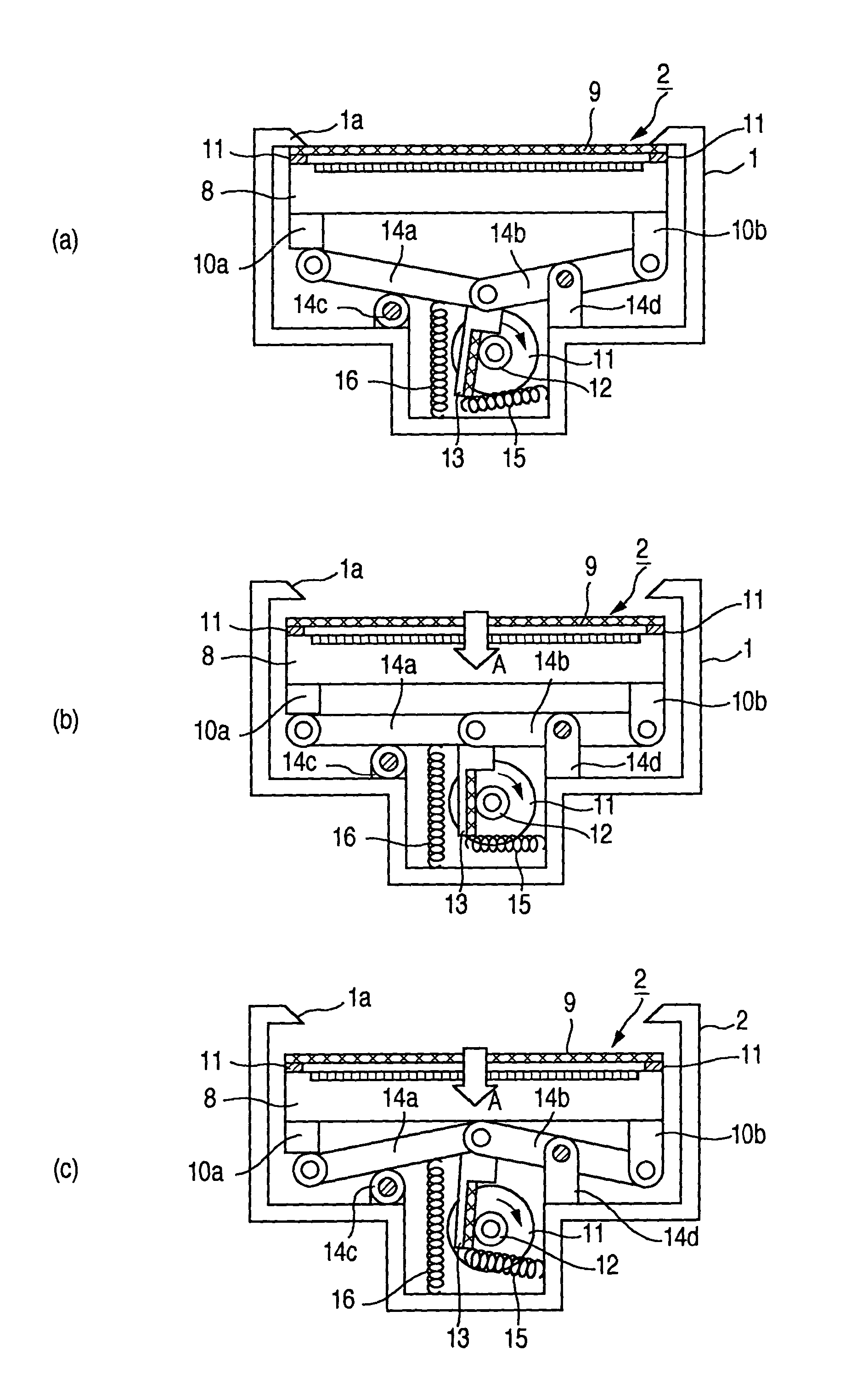
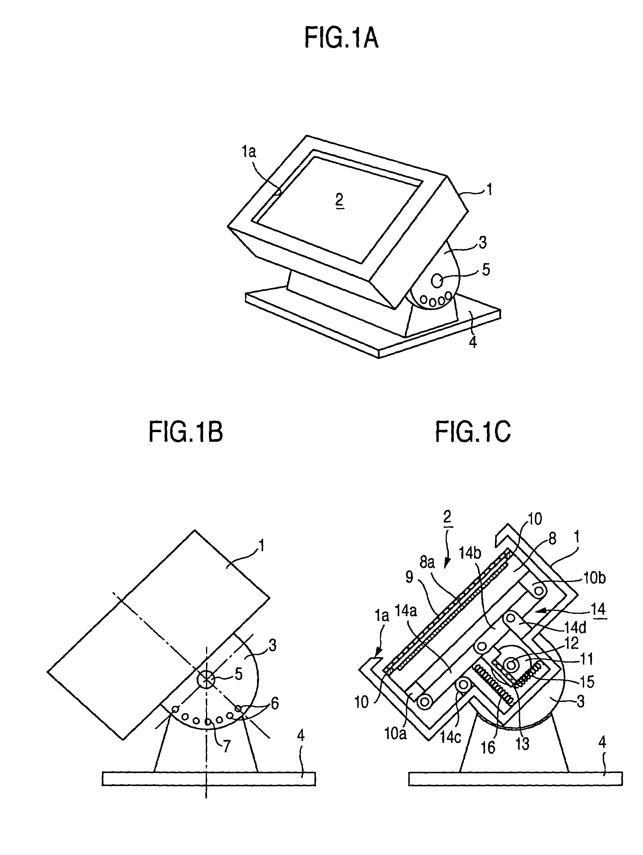
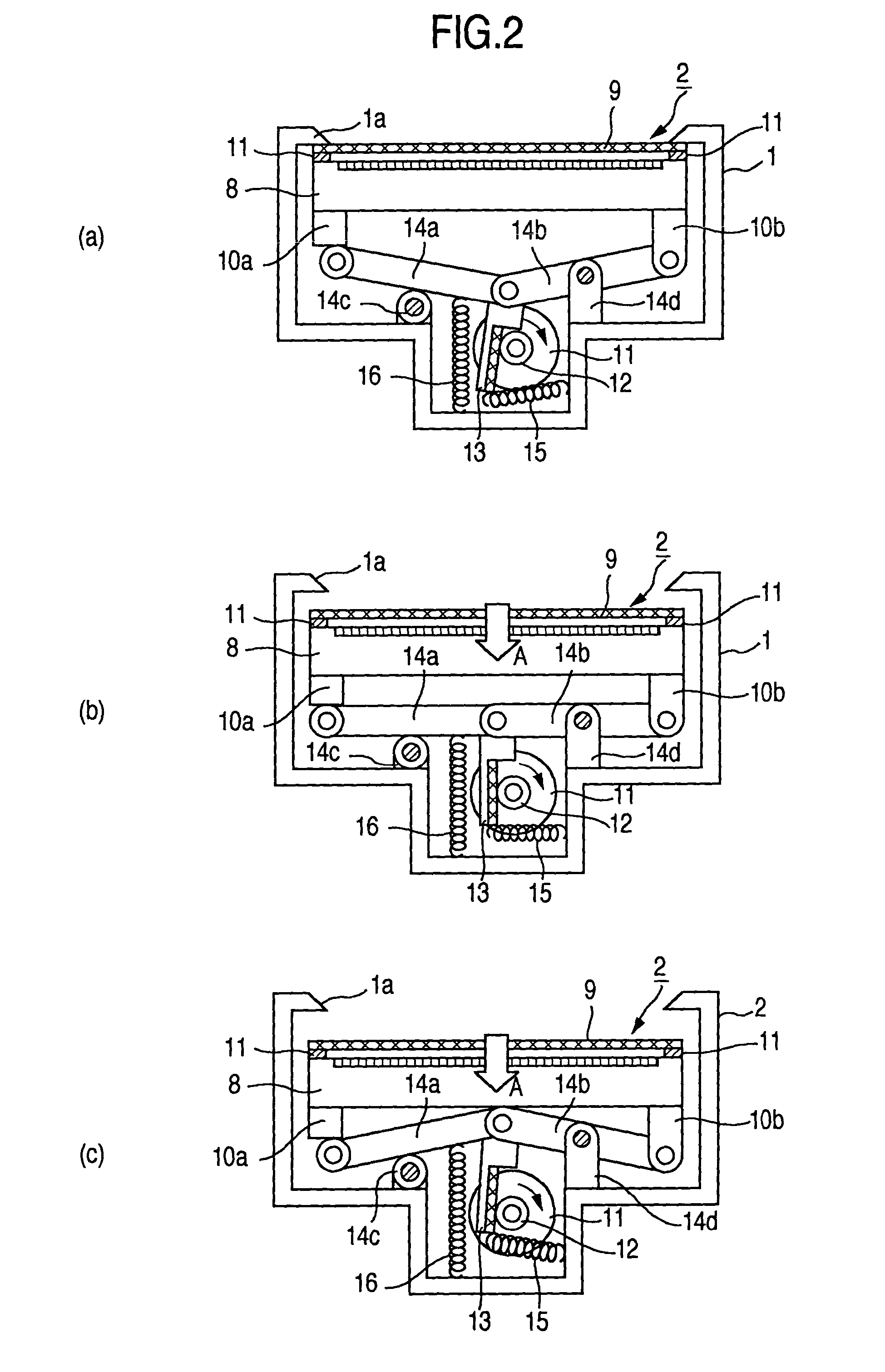
[0045]FIGS. 1A, 1B and 1C are configuration diagrams showing a display unit with touch panel according to the present invention. FIG. 1A is an oblique exterior view, and FIG. 1B is a side view. FIG. 1C is a sectional view. Reference numeral 1 denotes a cabinet, 1a an opening, 2 a display screen, 3 a fixture, 4 a stand, 5 an axis of rotation, 6 a pin hole, 7 a pin, 8 a display panel, 8a a display surface, 9 a touch panel, 10, 10a and 10b support members, 11 a drive motor, 12 a rotary gear, 13 a spur gear, 14 a link mechanism, 14a and 14b links, 14c and 14d support members, and 15 and 16 tension springs.

[0046]With reference to FIGS. 1A to 1C, a rectangular opening 1a is formed in the front face of a box-shaped cabinet 1. The display screen 2 is provided in the opening 1a. Although not illustrated, members that can be touched and operated, such as operation buttons and messages, (hereafter referred to as touch operation members) are displayed on the display screen 2. By conducting touc...

second embodiment

[0136]FIG. 13 is a diagram showing a concrete example of a picture displayed on the display screen 2 in the second embodiment by the control operation shown in FIG. 8.

[0137]With reference to FIG. 13, it is now supposed that operation buttons 24a to 24c are displayed on the display screen 2 and the fingertip 19 has touched the display screen 2. If the pressure P caused by the touch of the fingertip 19 and detected by the pressure sensor (FIG. 6) becomes P1≦P (the step 102), then the control section 20 detects the touch position of the fingertip 19 on the basis of a result detected by the touch sensor (FIG. 6), compares the touch position with data in the storage section 22 (FIG. 6), and thereby determines whether the touch position is in an area (here, in an area of one of the operation buttons 24a to 24c) where a predetermined function (i.e., the processing B and C) is to be executed (the step 103). If the touch position is, for example, in the area of the operation button 24b, then...

third embodiment

[0152]a display unit with touch panel according to the present invention will now be described.

[0153]In the same way as the first and second embodiments, the third embodiment also has the configuration shown in FIGS. 1A to 6. In the third embodiment, the display screen 2 can assume an arbitrary drive quantity.

[0154]FIG. 16 is a flow chart showing control operation of the control section 20 (FIG. 6) in the third embodiment. Hereafter, its operation will be described with reference to display examples on the screen.

[0155]FIGS. 17A, 17B and 17C show examples of a picture displayed on the display screen 2 in the control operation. It is now supposed that an initial position of the display screen 2 is an intermediate position between a position in the state shown in FIG. 2, (a) and a position in the state shown in FIG. 2, (c).

[0156]With reference to FIGS. 17A to 17C, if power supply, which is not illustrated, is turned on, then the control section 20 brings the display unit into the oper...


PUM


Abstract

There is provided a display unit including a touch panel disposed on a display screen of a display panel to detect a touch position of a pointing device, operation being conducted by touching a touch operation member displayed on the screen. The display unit includes a sensor for sensing a pushing pressure caused when touching the touch operation member, and a control section for conducting first processing concerning the touch operation member pushed by the pointing device when the pressure sensed by the sensing unit satisfies a first predetermined pressure condition, and conducting second processing concerning the touch operation member, when the pushing pressure has changed from the first condition to a second one. Upon the change from the first condition to the second one, a function of moving the screen in a direction of pushing pressure caused by the pointer is executed by the second processing.

Description

CROSS-REFERENCE TO RELATED APPLICATION[0001]The present application relates to subject matters described in application Ser. No. 10 / 230,100 filed on Aug. 29, 2002 assigned to the assignee of the present application. The disclosures of this application are incorporated herein by reference.BACKGROUND OF THE INVENTION[0002]The present invention relates to a display unit with touch panel used in terminal devices of installation type or portable type.[0003]In recent years, terminal devices have become widely used in various business worlds. For example, ATMs (Automatic Tellers Machines) are installed in banks, and ticket selling machines and map guide machines are installed at railroad stations. Thus, a part of business to be conducted in banks and at railroad stations can be executed. In stores such as fast-food stores as well, terminal devices are used for commodity order processing in some cases (as described in, for example, JP-A-5-216587). In addition, terminal devices that receive ...

Claims


Application Information

Patent Timeline
IPC IPC(8): G09G5/00G06F3/041F16M11/10G06F1/16G06F3/00G06F3/01G06F3/048G06F3/0481G06F3/0484G06F3/0488G07F19/00G09F9/00
CPCF16M11/10F16M11/18G06F1/1601G06F3/016G07F19/205G06F3/0418G06F3/0488G06F3/04883G07F19/20G06F3/041F16M2200/024
Inventor HOSHINO, TAKESHIMINEMOTO, TAKESHITSUKADA, YUJIN
Owner MAXELL HLDG LTD
Why Eureka
Try Eureka