Lens supporting frame of lens device and method of adjusting the same

a technology of lens supporting frame and lens supporting frame, which is applied in the field of lens supporting frame of lens supporting frame and the same, can solve the problems of difficult management and control of the direction and amount of a movement of apart of the lens supporting frame, increase in cost, etc., and achieves the effects of improving productivity, reducing labor intensity, and facilitating and accurately performing

Inactive Publication Date: 2008-02-05
FUJI PHOTO OPTICAL CO LTD
View PDF6 Cites 8 Cited by
  • Summary
  • Abstract
  • Description
  • Claims
  • Application Information

AI Technical Summary

Benefits of technology

[0006]An object of an illustrative, non-limiting embodiment of the invention is to overcome the disadvantages described above and to allow the inclination of a lens group with reference to an optical axis to be easily and accurately adjusted. Also, the invention is not required to overcome the disadvantage described above, and an illustrative, non-limiting embodiment of the invention may overcome a different disadvantage or may not overcome any disadvantages.
[0011]In the lens supporting frame and the method of adjusting the same according to the invention, it is possible to know the direction and amount of a movement of a part of the lens holder by checking the state of abutment between the ribs and the abutting parts. Further, an adjusting operation requires neither complicated apparatus nor skillfulness in the operation because it can be performed only by rotating the lens holder. Since the operation of adjusting the inclination of a lens group can be easily and accurately performed in a short time for those reasons, a lens device can be provided at a low cost with improved productivity. Further, since the inclination of each lens group can be accurately adjusted, it is possible to realize a difficult lens design for which accurate adjustment is a prerequisite.
[0012]Further, since the preliminary coupling units is provided on the lens holder and the moving frame, even when the user releases the lens holder on the way of adjustment, the adjustment which has been made until that time will not become useless, which contributes to an improvement of operational efficiency. Since the inclination of the lens holder can be further adjusted with the screws engaged with the moving frame after the adjustment using the ribs and the abutting parts, a wide range of adjustment can be achieved.

Problems solved by technology

However, according to the adjusting method utilizing eccentric rollers disclosed in JP-A-2003-202479, it is difficult to manage and control the direction and amount of a movement of apart of the lens supporting frame that is caused by a rotation of any of eccentric rollers associated with the three cam followers, and such an operation has been time-consuming and has therefore resulted in a cost increase.

Method used


Image

  • Lens supporting frame of lens device and method of adjusting the same
  • Lens supporting frame of lens device and method of adjusting the same
  • Lens supporting frame of lens device and method of adjusting the same

Examples


Embodiment Construction

[0027]An exemplary embodiment of the invention will now be described with reference to drawings.

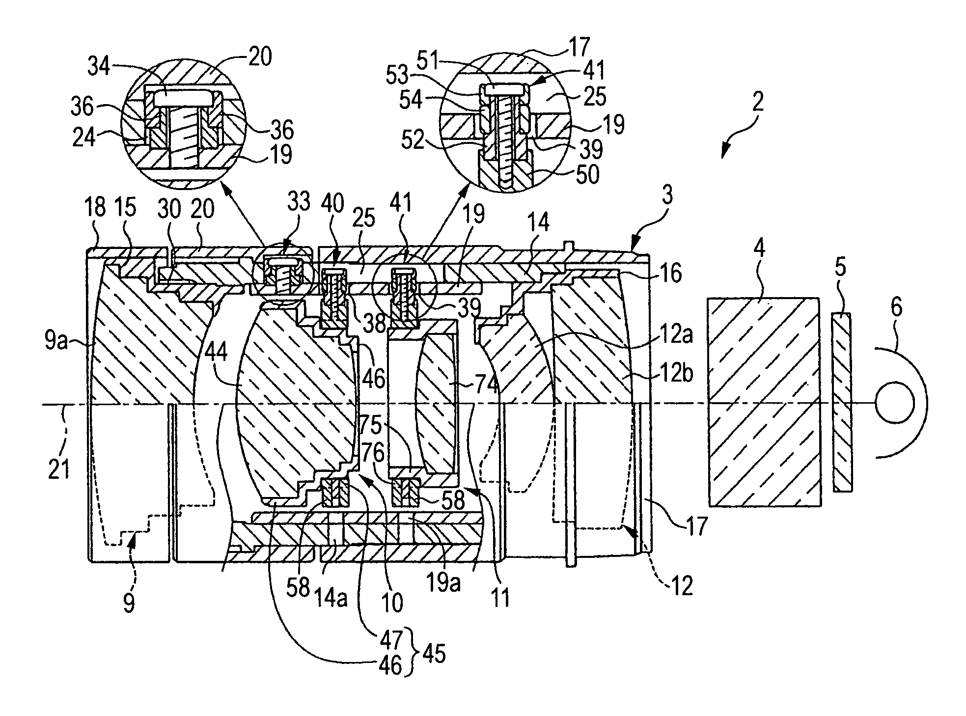
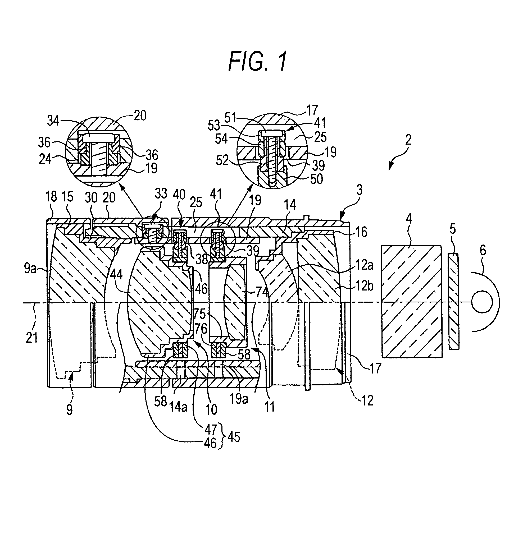
[0028]FIG. 1 shows an image projection unit of a projector. An image projection unit 2 includes a zoom lens device 3, a dichroic prism 4, a transmissive image display 5 such as an LCD, and a projection lamp 6. Light emitted by the projection lamp 6 is transmitted by the transmissive image display 5 to enter the dichroic prism 4. Images in RGB type three primary colors displayed on the transmissive image display 5 are synthesized by the dichroic prism 4, and the resultant image is projected on a screen by the zoom lens device 3.

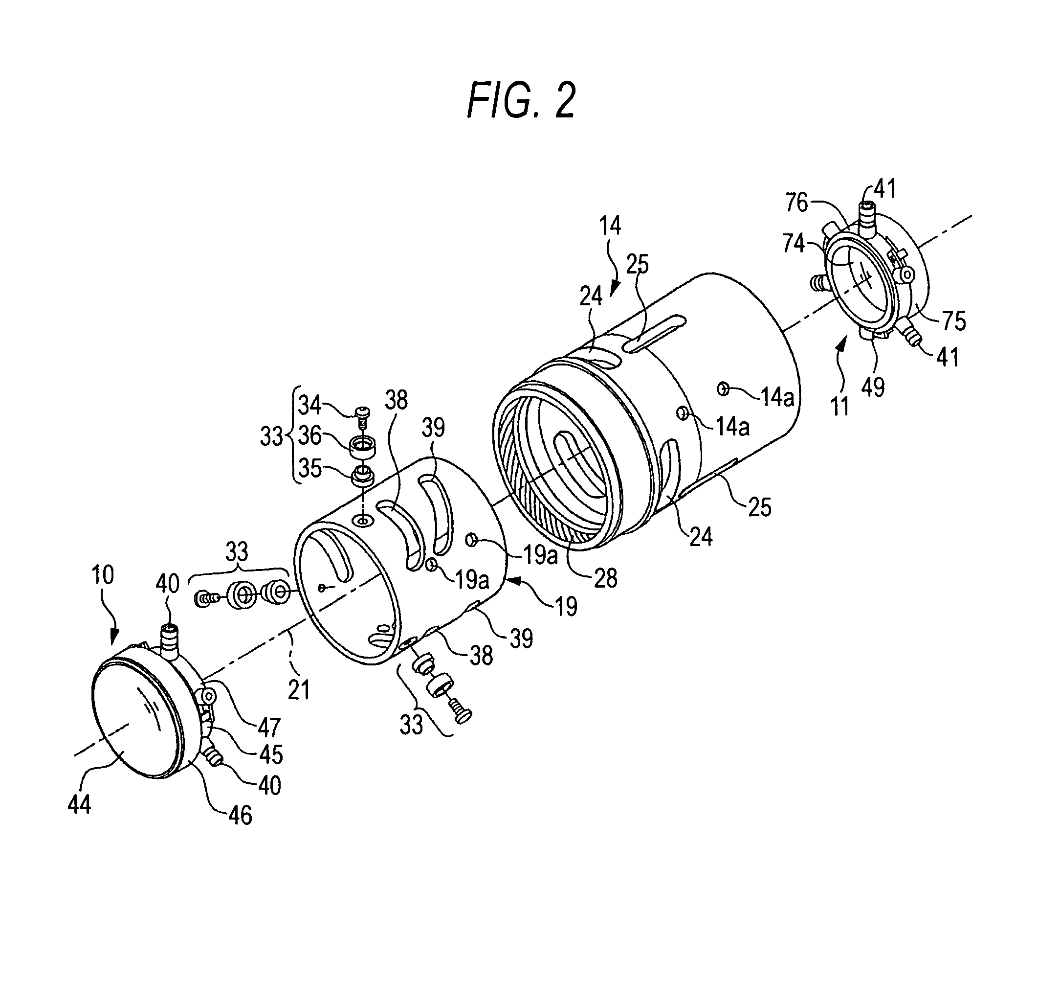
[0029]The zoom lens device 3 includes a first lens group 9 serving as a front converter having a focusing function, a second lens group 10 serving as a variator, a third lens group 11 serving as a compensator, a fourth lens group 12 serving as a relay lens, a fixed cylinder 14, a focus cylinder 15, a relay cylinder 16, an outer cylinder 17, a focus ring 18, a zoom c...


PUM


Abstract

A lens supporting frame is provided and includes a lens holder supporting a lens and a moving frame which is fitted to a cylindrical part of the lens holder to support the same. Ribs are provided at equal intervals in a rotation direction on a rear end face of the lens holder, the ribs having a plurality of inclined surfaces inclined respectively toward the front or rear ends of an optical axis. Abutting parts are provided on a rear end face of the moving frame so as to abut on the ribs. When the lens holder is rotated after mounting it in the moving frame, parts of the lens holder facing the abutting parts are moved in directions along the optical axis as a result of abutment between the inclined surfaces of the ribs and the abutting parts to change the inclination of the lens holder relative to the optical axis.

Description

FIELD OF THE INVENTION[0001]The present invention relates to a lens device in which a plurality of lens groups are mounted in a cam cylinder and in which the lens groups are moved in a direction along the optical axis of the device through a rotation of the cam cylinder and, more particularly, to a structure of a lens frame for supporting the lenses and a method of adjusting the same.BACKGROUND OF THE INVENTION[0002]A zoom lens device which is a lens device capable of obtaining different focal lengths alone has been used in optical products such as cameras and projectors. In such a zoom lens device, as disclosed in JP-A-2003-202479, a plurality of lens groups is mounted in a mirror barrel, and the lens groups are moved in directions along the optical axis to vary the magnification and to perform focusing.[0003]Each of the lens groups includes at least one lens and an annular lens supporting frame for supporting the lens. For example, three cam followers in the form of pins are radia...

Claims


Application Information

Patent Timeline
Patent Type & Authority Patents(United States)
IPC IPC(8): G02B7/02G02B15/14
CPCG02B7/10
Inventor SAKAMOTO, KENICHIMASUZAWA, TOMONARIARAKI, TAKAO
Owner FUJI PHOTO OPTICAL CO LTD
Why Eureka
Try Eureka