Digital transmitter/receiver system having a robust error correction coding/decoding device and error correction coding/decoding method thereof

a digital transmitter/receiver system and error correction coding/decoding technology, applied in the direction of coding, code conversion, selective content distribution, etc., can solve the problem that the error correction coding method of the existing atsc transmission system cannot guarantee the stable receiving of data in the inferior channel environment, and achieve the effect of strong error correction

Active Publication Date: 2008-02-26
SAMSUNG ELECTRONICS CO LTD
View PDF17 Cites 45 Cited by
  • Summary
  • Abstract
  • Description
  • Claims
  • Application Information

AI Technical Summary

Benefits of technology

[0014]The present invention has been developed in order to solve the above drawbacks and other problems associated with the conventional arrangement. An aspect of the present invention is to provide a digital transmitter / receiver system having a strong error correction coding / decoding device that can guarantee a receiving performance in an inferior channel environment, and an error correction coding / decoding method thereof.
[0025]Accordingly, the transmitter generates parities of the predetermined number of bytes included in the packets and the predetermined number of parity packets, and the receiver performs an error correction using the parities of the predetermined number of bytes and the predetermined number of parity packets, so that a stronger error correction can be achieved.

Problems solved by technology

However, the error correction coding method of the existing ATSC transmission system cannot guarantee a stable receiving of data in the inferior channel environment where many errors occur.

Method used


Image

  • Digital transmitter/receiver system having a robust error correction coding/decoding device and error correction coding/decoding method thereof
  • Digital transmitter/receiver system having a robust error correction coding/decoding device and error correction coding/decoding method thereof
  • Digital transmitter/receiver system having a robust error correction coding/decoding device and error correction coding/decoding method thereof

Examples


Embodiment Construction

[0038]Certain embodiments of the present invention will be described in greater detail with reference to the accompanying drawings.

[0039]In the following description, same drawing reference numerals are used for the same elements even in different drawings. The matters defined in the description such as a detailed construction and elements are nothing but the ones provided to assist in a comprehensive understanding of the invention. Thus, it is apparent that the present invention can be carried out without those defined matters. Also, well-known functions or constructions are not described in detail since they would obscure the invention in unnecessary detail.

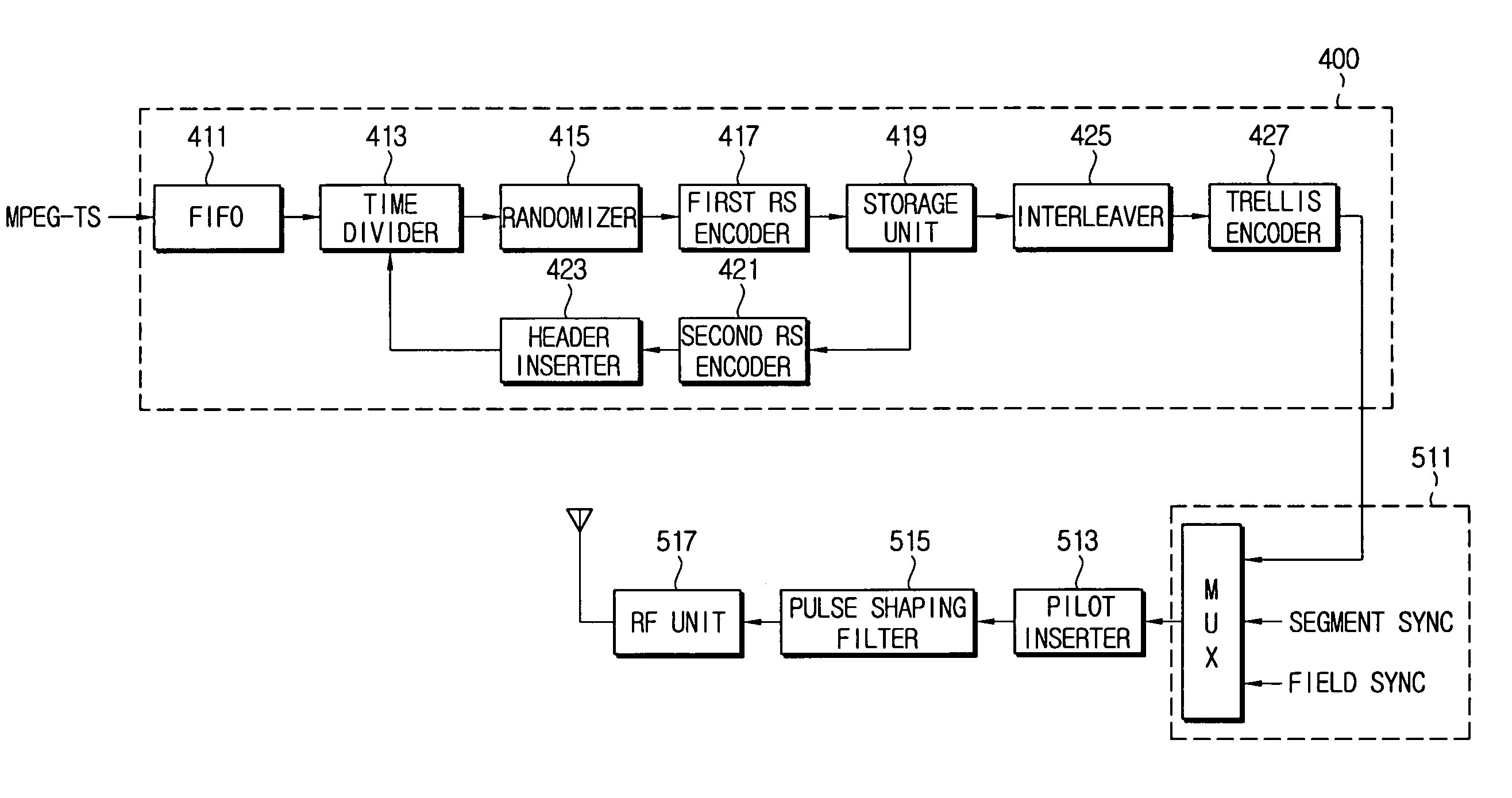
[0040]FIG. 4 is a schematic block diagram of a digital transmitter system having an error correction coding device according to an embodiment of the present invention.

[0041]The digital transmitter system includes an error correction coding device 400 according to the present invention, a sync inserter 511, a pilot inserter 513,...


PUM


Abstract

An error correction coding device includes a time divider for dividing field data of L packets into N data packets and (L-N) parity packets, a first RS (Reed-Solomon) encoder adding parities of a predetermined number of bytes to the data packets, respectively, a storage unit for storing the data packets, and a second RS encoder generating parity packets corresponding to the stored data packets. An error correction decoding device includes a first RS decoder correcting errors in a horizontal direction of the field data using parities of the predetermined number of bytes included in the L packets, a storage unit storing the error-corrected data packets, and a second RS decoder correcting errors in a vertical direction of the field data using the parity packets. Thus, the error correction can be strongly performed using parities existing in the horizontal and vertical directions with respect to the field data.

Description

[0001]This application claims the benefit of U.S. Provisional Patent Application Nos. 60 / 478,342 filed Jun. 16, 2003 and 60 / 495,873 filed Aug. 19, 2003 in the U.S. Patent and Trademark Office, and Korean Patent Application No. 2003-67522 filed Sep. 29, 2003 in the Korean Intellectual Property Office, the disclosures of which are incorporated herein by reference.BACKGROUND OF THE INVENTION[0002]1. Field of the Invention[0003]The present invention relates to a digital transmitter / receiver system, and more particularly to an error correction coding / decoding device and method for a digital transmitter / receiver system.[0004]2. Description of the Related Art[0005]FIG. 1 is a schematic block diagram of an error correction coding device of a transmitter system of the United States ATSC standard. Referring toFIG. 1, the error correction coding device 100 includes a randomizer 111, an RS (Reed-Solomon) encoder 113, an interleaver 115, and a trellis encoder 117.[0006]Here, it is exemplified th...

Claims


Application Information

Patent Timeline
Patent Type & Authority Patents(United States)
IPC IPC(8): H03M13/11H03M13/29
CPCH03M13/2906H03M13/2909H03M13/2927H03M13/2948H04L1/0042H04L1/0057H04L1/0065H04N21/2383H04N21/4382H04N21/44209H04N21/4425H03M13/1515H03M13/251H03M13/2936H03M13/11
Inventor CHANG, YONG-DEOKPARK, SUNG-WOO
Owner SAMSUNG ELECTRONICS CO LTD
Why Eureka
Try Eureka