Monolithic air conditioner

a monolithic air conditioner and air filter technology, applied in the field of monolithic air conditioners, can solve the problems of increasing the cost the air leakage occurs, and the complexity of the monolithic air conditioner b>10/b> becomes complicated, so as to improve reduce the cost. , the effect of improving the air discharging structur

Active Publication Date: 2008-03-11
LG ELECTRONICS INC
View PDF15 Cites 4 Cited by
  • Summary
  • Abstract
  • Description
  • Claims
  • Application Information

AI Technical Summary

Benefits of technology

[0018]An object of the present invention is to provide a monolithic air conditioner that can be manufactured with fewer components and less manufacturing cost and through a simplified assembly process.
[0019]Another object of the present invention is to provide a monolithic air conditioner that can reduce pneumatic resistance of indoor air and outdoor air by increasing it inner space.
[0024]According to the present invention, the monolithic air conditioner is manufactured with fewer components, so that the monolithic air conditioner can be manufactured through a simplified assembly process with less cost.
[0025]Also, the inner space of the monolithic air conditioner increases and thus sucked indoor and outdoor air can flow smoothly in the monolithic air conditioner. Therefore, pneumatic resistance can be reduced.
[0026]Further, the monolithic air conditioner has an improved air discharging structure, so that discharging indoor air can be prevented from leakage and reversely flowing to the indoor heat exchanger.
[0027]In addition, the air guide is securely fixed to the scroll, so that the air guide can be prevented from shaking due to vibration generated during the operation of the monolithic air conditioner.

Problems solved by technology

Further, assembling process of monolithic air conditioner 10 becomes complicated and the cost of the monolithic air conditioner 10 increases.
In addition, air leakage occurs when the sucked indoor air is discharged from the monolithic air conditioner 10.

Method used


Image

  • Monolithic air conditioner
  • Monolithic air conditioner
  • Monolithic air conditioner

Examples


Embodiment Construction

[0045]Reference will now be made in detail to the preferred embodiments of the present invention, examples of which are illustrated in the accompanying drawings.

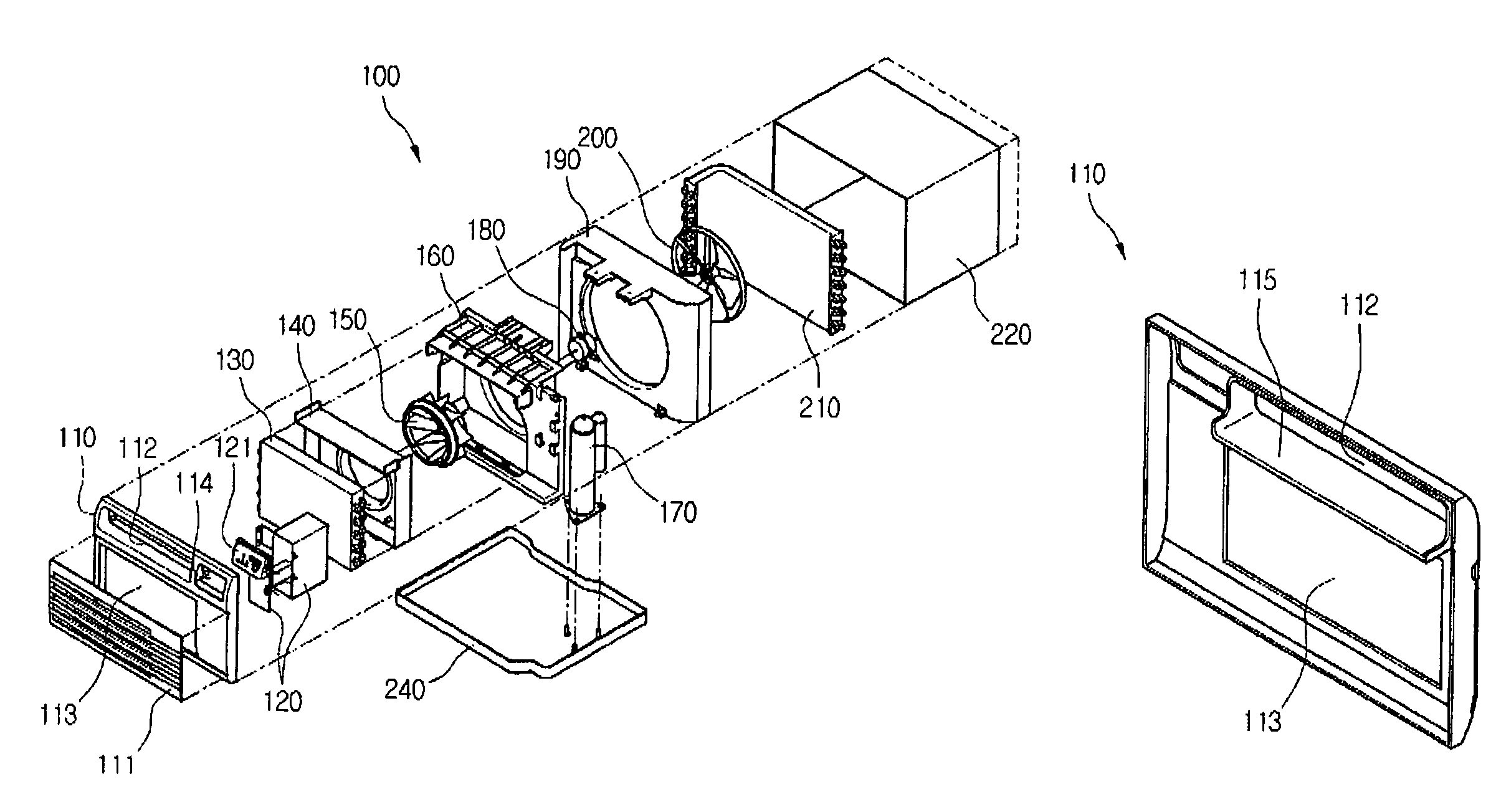
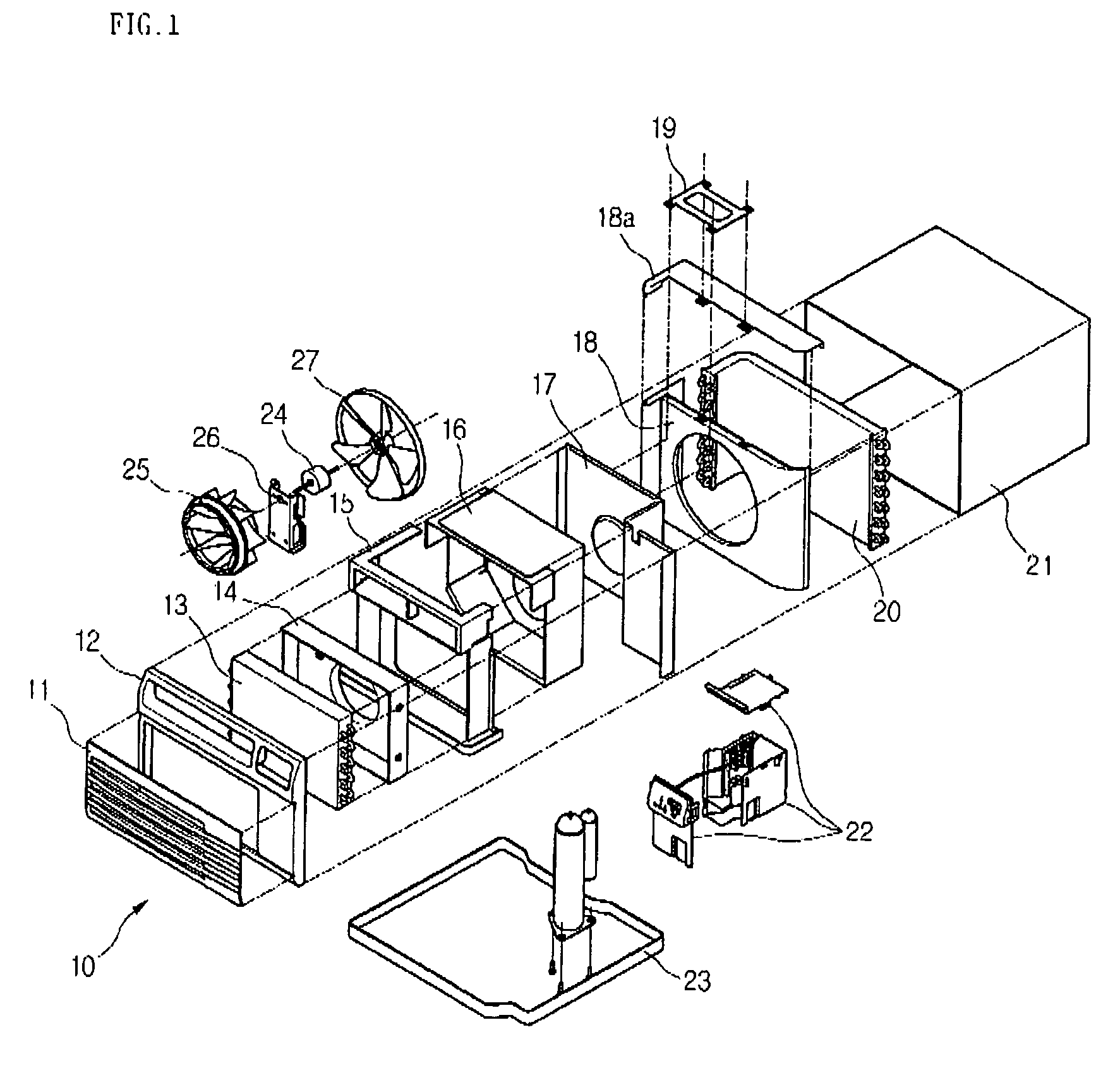
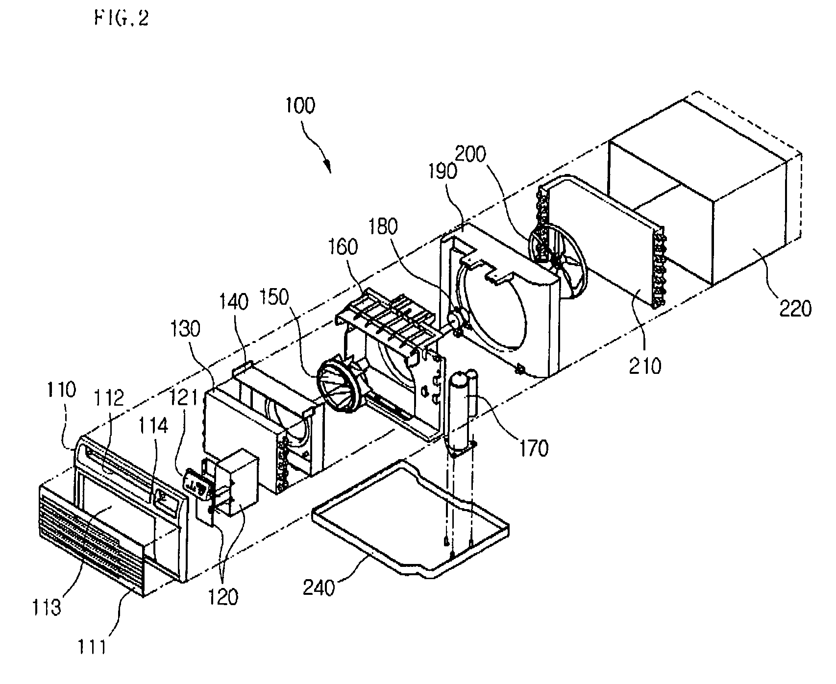
[0046]FIG. 2 is an exploded perspective view of a monolithic air conditioner according to the present invention, and FIG. 3 is a side-sectional view of the monolithic air conditioner depicted in FIG. 2.

[0047]Referring to FIGS. 2 and 3, a monolithic air conditioner 100 includes a cabinet 220 defining an outer appearance, a front panel 110 mounted on a front portion of the cabinet 220, a front grill 111 mounted on a front surface of the front panel 110 to guide airflow, an indoor heat exchanger 130 disposed in rear of the front panel 110 to allow introduced air to be heat-exchanged with a refrigerant, and a control box 120 disposed in rear of the front panel 110.

[0048]The front panel 110 is provided with an indoor air intake 113 on which the front grill 111 is mounted to allow the air to be introduced into the air conditioner ...


PUM


Abstract

In a monolithic air conditioner, a front panel is mounted on a front of a cabinet and includes an indoor air intake, an indoor air outlet, and a discharge guide backwardly extended from the indoor air outlet. An indoor heat exchanger is mounted on a back of the front panel. An air guide on which the indoor heat exchanger is mounted includes an orifice in a center to pass sucked indoor air therethrough. A scroll is mounted on a back of the air guide to guide the sucked indoor air. An indoor fan is mounted between the scroll and the air guide to suck the indoor air. A shroud is mounted on a back of the scroll to guide sucked outdoor air and it defines an orifice in a center to discharge the sucked outdoor air. An outdoor fan is mounted on a back of the shroud to suck the outdoor air, a fan motor is mounted on the scroll to drive the indoor and outdoor fans, and an outdoor heat exchanger is mounted on a back of the outdoor fan to exchange heat with the sucked outdoor air.

Description

BACKGROUND OF THE INVENTION[0001]1. Field of the Invention[0002]The present invention relates to an air conditioner, and more particularly, to a monolithic air conditioner that is designed to have a sufficient airflow space by reducing parts and to have an improved air discharge structure to prevent discharging air from leaking through other places other than an indoor air outlet.[0003]2. Description of the Related Art[0004]Generally, an air conditioner is operated as a refrigerant goes through a cooling cycle having a series of processes such as a compression process, a condensing process, an expanding process, and a vaporizing process. That is, after the refrigerant is compressed to a high temperature and pressure state, heat is discharged to an outer side by a condenser. Then, the temperature and pressure of the refrigerant are lowered as it goes through an expansion valve. Then, the refrigerant goes through the vaporizer to absorb heat and returns to the condenser.[0005]Here, th...

Claims


Application Information

Patent Timeline
Patent Type & Authority Patents(United States)
IPC IPC(8): F25D23/12F25D19/00
CPCF24F1/027F24F13/20F24F2013/207
Inventor HA, JONG MINMIN, SEONG KYUKIM, TAI HOONJANG, WON SUKKIM, BYEONG GI
Owner LG ELECTRONICS INC
Why Eureka
Try Eureka