Printhead carriage

a printing head and carriage technology, applied in printing, other printing apparatus, power drive mechanisms, etc., can solve the problems of difficult to compensate for thermal expansion, the mounting plate is subject to thermal expansion, and the heat is considerable, and achieves stable holding of the mounting plate, high adjustment accuracy, and simple construction

Inactive Publication Date: 2008-09-02
OCE TECH
View PDF4 Cites 3 Cited by
  • Summary
  • Abstract
  • Description
  • Claims
  • Application Information

AI Technical Summary

Benefits of technology

[0006]The present invention provides a printhead carriage in which the mounting structure has a simple construction but nevertheless is capable of stably holding the mounting plate in position with a high adjustment accuracy.
[0008]The use of a framework of such hinge plates has the advantage that the mounting plate can stably be supported in the desired position, and the elasticity of the hinges may be utilized for a precise fine-adjustment of the mounting plate. The hinge plates are rigid in one direction, i.e., their longitudinal direction, but behave like leaf springs with a relatively high spring constant in a direction normal to the longitudinal direction and in the same plane of the hinge plate. Thus, a portion of the mounting plate that is connected to a hinge plate may be rigidly supported in the one direction and may be adjusted in the direction orthogonal to the said one direction.
[0010]The relatively high spring constant of the elastic hinges has the effect that the resonance frequency of the mounting plate will be high and will thus be sufficiently offset from the spectrum of exciting frequencies that are to be expected when the printer is operating. Thus, vibrations of the mounting plate can be successfully suppressed.
[0011]The elasticity of the hinges also permits the absorption of thermal expansions and contractions of the mounting plate. Another remarkable advantage results from the fact that the narrow hinge portions have a very low heat conductivity, even, for example, when the hinge plates are made of spring steel, so that a good thermal insulation of the mounting plate is achieved and dissipation of heat through the suspension structure is effectively suppressed. As a result, a uniform temperature profile of the mounting plate can be achieved, so that the compensation of thermal expansions is facilitated, and, in the case of a hot melt ink jet printer, losses of heat energy are reduced to a minimum.
[0013]Preferably, the mounting plate is a rectangular plate having two support points projecting from the shorter sides of the rectangle, and a third support point projecting from one of the longer sides of the rectangle. An adjusting unit may be associated with each of the three support points. Then, the adjustable degrees of freedom of the mounting plate may comprise the positions of the three support points in a direction Z normal to the plane of the mounting plate. These degrees of freedom permit a control of the distance between the mounting plate and the print surface of the printer as well as the parallelism between the mounting plate and the print surface. One of the three adjusting units may be one with two degrees of freedom, so that it is additionally possible to adjust the position of the associated support point in a direction X that is parallel to the side of the mounting plate from which this support point projects. An adjustment in the X-direction will cause the mounting plate to rotate about an axis normal to the plane of the mounting plate and thus permits a control of the skew angle of the mounting plate relative to the main scanning direction Y.

Problems solved by technology

If the carriage carries a plurality of printheads, as is the case for example in a multi-color printer, another problem may arise from the fact that the operation of the printheads is frequently accompanied by the generation of a considerable amount of heat, so that the mounting plate is subject to thermal expansion which may change the positions of the printheads relative to one another.
However, if the temperature distribution of the mounting plate is not uniform, it becomes difficult to compensate for the thermal expansion.
As a result, considerable forces of inertia are generated which may cause the mounting plate to shift or to vibrate.

Method used


Image

  • Printhead carriage
  • Printhead carriage
  • Printhead carriage

Examples


Embodiment Construction

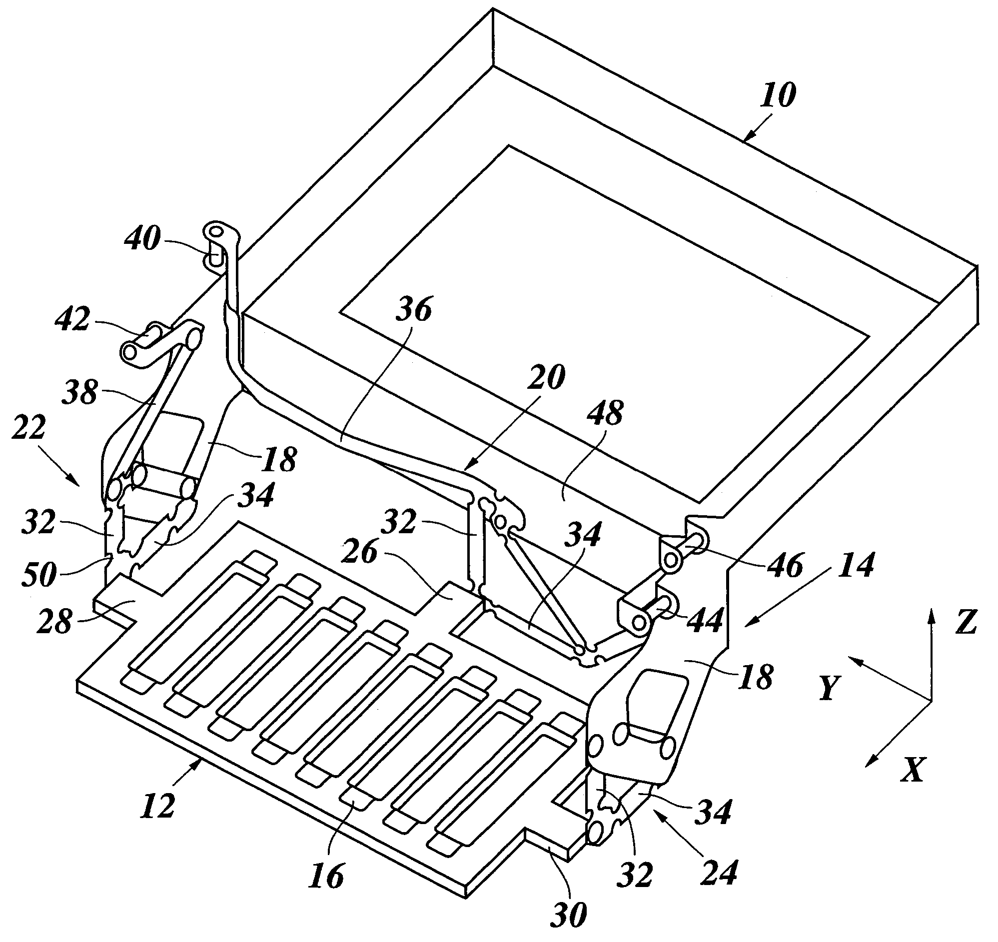
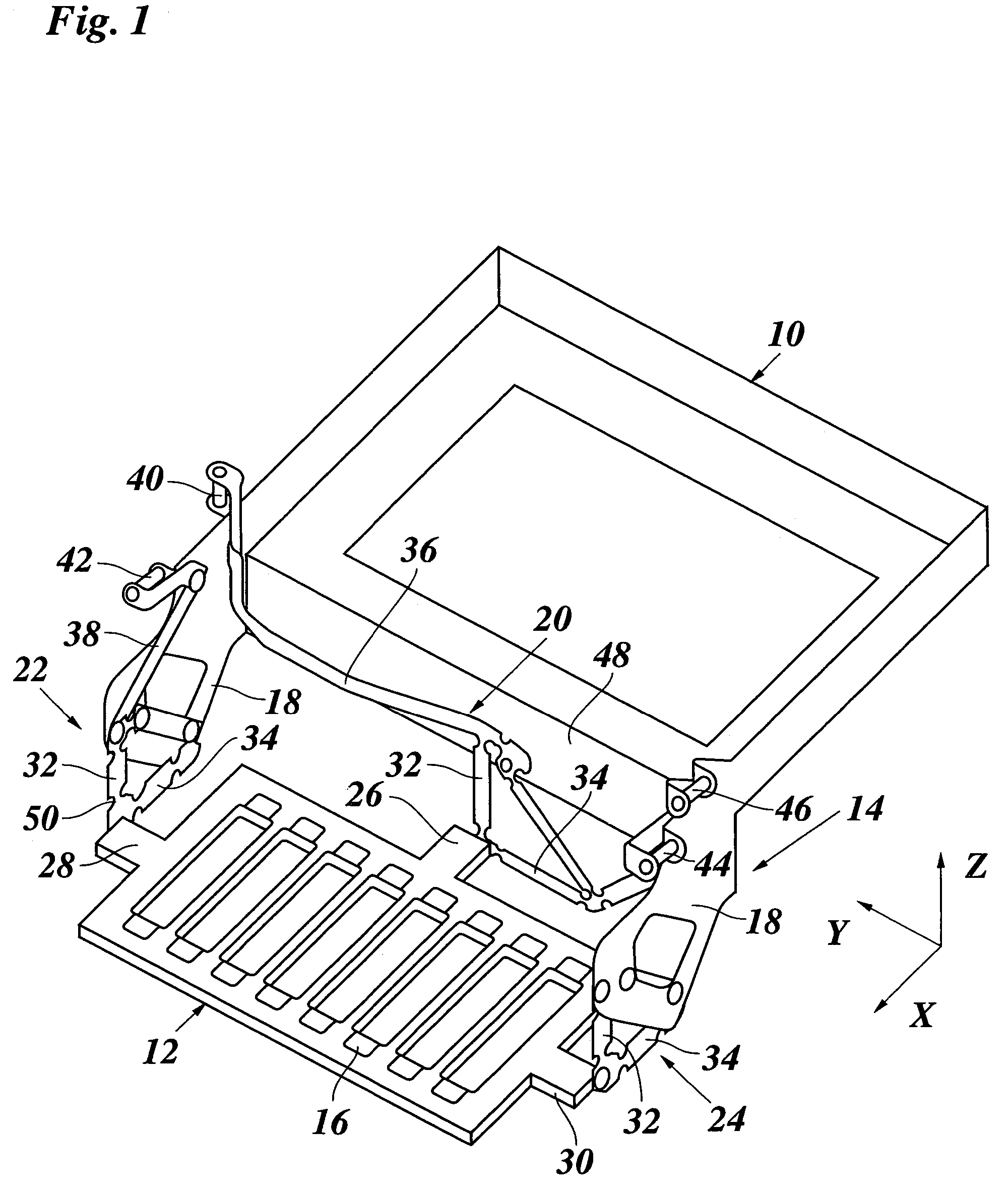
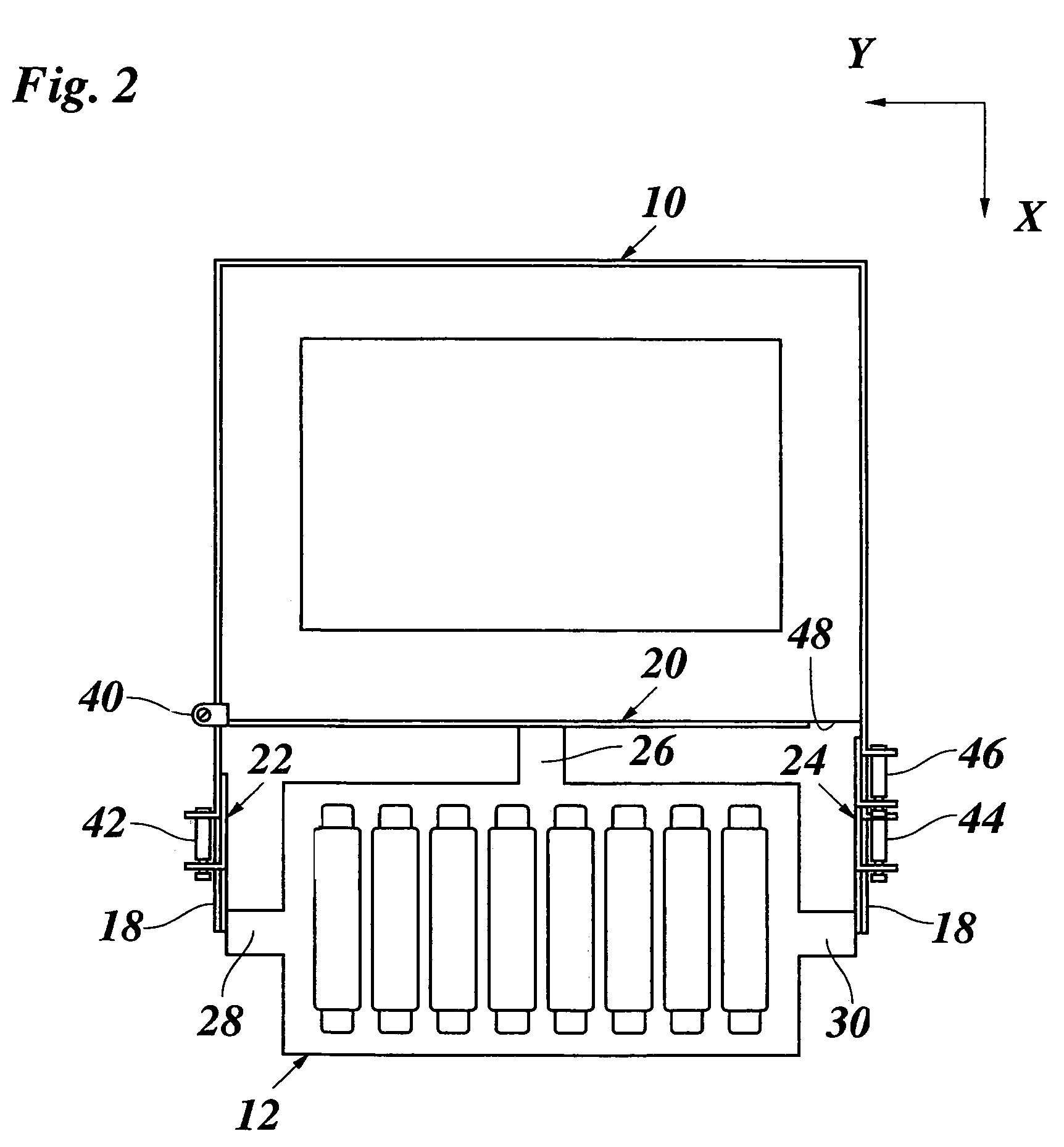
[0020]The printhead carriage shown in FIG. 1 comprises a body 10, a printhead mounting plate 12 made of metal, and a suspension structure 14 which adjustably connects the mounting plate 12 to the body 10.

[0021]As is commonly known in the art, the body 10 is guided on a guide rail (not shown) which extends in Y-direction of a Cartesian coordinate system X, Y, Z shown in FIG. 1. The mounting plate 12 has eight sockets 16 adapted to accommodate a corresponding number of ink jet printheads (not shown). The printheads, e.g., hot-melt ink jet printheads, will thus be held in a position in which downwardly directed nozzles of the printheads, which all lie in a common plane, will face a print surface (not shown) of the printer, with only a small gap being formed between the plane of the nozzles and the surface of a recording medium that is supported on the print surface.

[0022]The suspension structure 14 is formed by two cantilever arms 18 of the body 10 and three adjusting units 20, 22, 24 ...


PUM


Abstract

A printhead carriage including a body that is guided and driven for reciprocating movement in a printer, a mounting plate for a printhead assembly, and a suspension structure adjustably connecting the mounting plate to the body, the suspension structure having a framework of hinge plates having elastic hinges and at least one adjusting mechanism adapted to adjust the position of the mounting plate by elastically deflecting at least one of the hinges. An adjusting unit which provides for at least one degree of freedom of the mounting plate and includes two hinge plates that are connected to a common support point of the mounting plate and are oriented at right angles relative to one another, and the adjusting mechanism is adapted to push and / or pull one hinge plate in the longitudinal direction thereof, with the elastic deflection of at least one hinge of the other hinge plate.

Description

[0001]This application claims priority to European Patent Application No. 04107044.2 filed on Dec. 29, 2004 in Europe, the entire contents of which is hereby incorporated by reference in its entirety.BACKGROUND OF THE INVENTION[0002]The present invention relates to a printhead carriage including a body that is guided and driven for reciprocating movement in a printer, a mounting plate for a printhead assembly, and a suspension structure adjustably connecting the mounting plate to the body, the suspension structure comprising a framework of hinge plates having elastic hinges that are formed by reduced-width portions of the hinge plates and at least one adjusting mechanism adapted to adjust the position of the mounting plate by elastically deflecting at least one of the hinges.[0003]In a scanning-type printer, e.g. an ink jet printer, a printhead carriage is moved back and forth in a main scanning direction Y, so as to scan a recording medium that is advanced step-wise in a sub-scanni...

Claims


Application Information

Patent Timeline
Patent Type & Authority Patents(United States)
IPC IPC(8): B41J23/00B41J29/13
CPCB41J2/17593B41J25/304B41J2202/14
Inventor NELLEN, WILHELMUS H. J.
Owner OCE TECH
Why Eureka
Try Eureka