Method and apparatus for graphically displaying call signaling flows in a network

a call signaling flow and network technology, applied in the field of method and apparatus for graphically displaying call signaling flow in a network, can solve the problems of call setup failure, procedure can consume a considerable amount of time, and is not a convenient method for locating service disruption areas

Active Publication Date: 2008-11-04
AMERICAN TELEPHONE & TELEGRAPH CO
View PDF8 Cites 9 Cited by
  • Summary
  • Abstract
  • Description
  • Claims
  • Application Information

AI Technical Summary

Problems solved by technology

Occasionally, routing configurations errors happen and messages between these network elements get into a looping pattern that creates call setup failures.
During these occasions of service disruptions, the network operators and engineers often have t

Method used


Image

  • Method and apparatus for graphically displaying call signaling flows in a network
  • Method and apparatus for graphically displaying call signaling flows in a network
  • Method and apparatus for graphically displaying call signaling flows in a network

Examples


Embodiment Construction

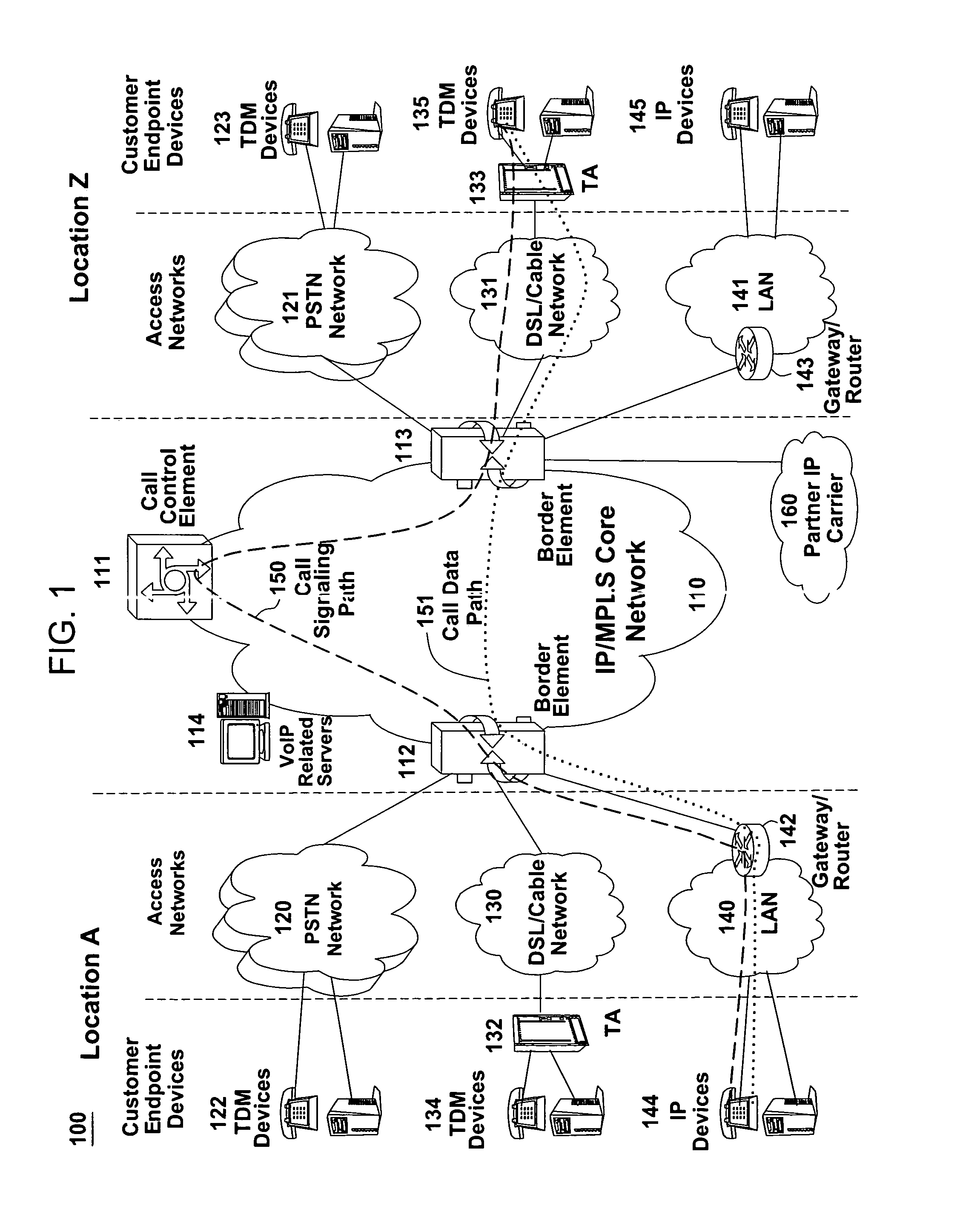
[0013]To better understand the present invention, FIG. 1 illustrates an example network, e.g., a packet-switched network such as a VoIP network related to the present invention. The VoIP network may comprise various types of customer endpoint devices connected via various types of access networks to a carrier (a service provider) VoIP core infrastructure over an Internet Protocol / Multi-Protocol Label Switching (IP / MPLS) based core backbone network. Broadly defined, a VoIP network is a network that is capable of carrying voice signals as packetized data over an IP network. An IP network is broadly defined as a network that uses Internet Protocol to exchange data packets.

[0014]The customer endpoint devices can be either Time Division Multiplexing (TDM) based or IP based. TDM based customer endpoint devices 122, 123, 134, and 135 typically comprise of TDM phones or Private Branch Exchange (PBX). IP based customer endpoint devices 144 and 145 typically comprise IP phones or PBX. The Ter...


PUM


Abstract

A method and system for graphically displaying call signaling flows for a communications network is described. In one example, a call flow alarm indicating an improper call signaling flow for a call is received. A respective projected call signaling flow associated with the call is then obtained. Lastly, the improper call signaling flow and the respective projected call signaling flow are graphically displayed.

Description

[0001]The present invention relates generally to communication networks and, more particularly, to a method and apparatus for graphically displaying call signaling flows in communications network, e.g., a Voice over Internet Protocol (VoIP) network.BACKGROUND OF THE INVENTION[0002]VoIP network service infrastructures contain different network elements that need to communicate with each other in order for calls to be setup and media paths established. For example, a Call Control Element (CCE), needs to communicate to routing databases and Border Elements (BE), and occasionally to Application Servers (AS). Broadly defined, a CCE is a network element that performs call control functions to setup a call, an AS is a network element that comprises the data as well as applications that the CCE needs in order to setup a call, and a Border Element is a network element that represents the edge of a VoIP network and serves as a gateway between a customer's network, a VoIP network, and a Public...

Claims


Application Information

Patent Timeline
IPC IPC(8): H04M3/22H04L12/26
CPCH04L41/22H04L41/5087H04M3/2281H04M7/006H04M7/0093
Inventor CROAK, MARIANESLAMBOLCHI, HOSSEIN
Owner AMERICAN TELEPHONE & TELEGRAPH CO
Why Eureka
Try Eureka