Card connector

a card connector and card slot technology, applied in the direction of coupling device connection, coupling/disconnecting parts, instruments, etc., can solve the problem that the structural complexity of the current locking mechanism needs improvement, and achieve the effect of effective engagement and prevention

Active Publication Date: 2009-02-17
TAI SOL ELECTRONICS +1
View PDF8 Cites 20 Cited by
  • Summary
  • Abstract
  • Description
  • Claims
  • Application Information

AI Technical Summary

Benefits of technology

[0006]The primary objective of the present invention is to provide a card connector, which provides a new locking mechanism that is structurally simple, of secure locking, and can effectively engage and prevent an electronic card inserted therein from falling-off.

Problems solved by technology

As stated above, the currently available locking mechanisms are structurally complex to need improvement.

Method used


Image

  • Card connector
  • Card connector
  • Card connector

Examples


Embodiment Construction

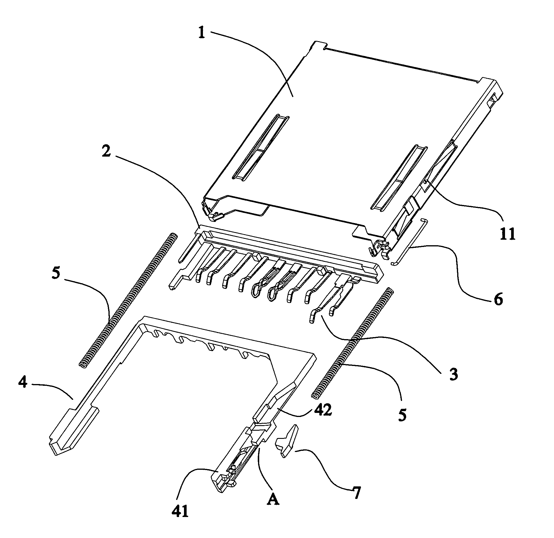
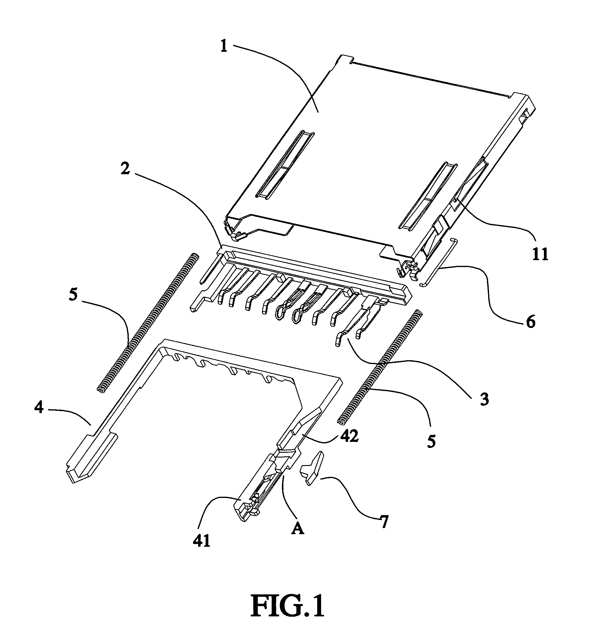
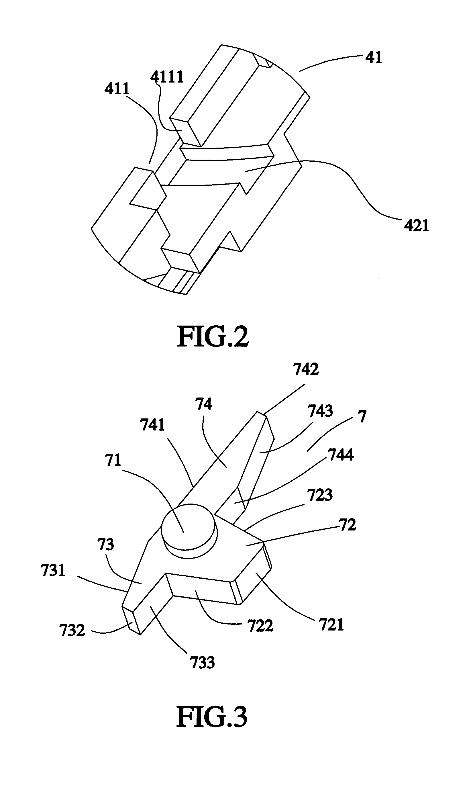
[0021]Referring to FIGS. 1-3, a card connector constructed according to a first embodiment of the present invention is composed of a housing 1, a base 2, a plurality of terminals 3, a slidable member 4, a spring 5, a guiding bar 6, and a hooked member 7. The housing 1 includes a tongue 11 provided on a sidewall thereof and having a front arm 111, a rear arm 112, and a bended portion provided between the front and rear arms 111 and 112. The terminals 3 are mounted in the base 2. The spring 5, the slidable member 4, and the base 2 are mounted in the housing 1. The housing 1, the base 2, and the slidable member 4 define a receiving chamber thereamong for receiving a memory card having a locating recess. The slidable member 4 includes a sidewall 41, a recession 42 formed on the sidewall 41 and close to an external side thereof, an opening 411 formed on an internal side of the sidewall 41, an end face 4111 provided on the sidewall 41 and abutting the opening 411, and a groove 421 provide...


PUM


Abstract

A card connector includes a housing, a base, a slidable member, three of which are provided in the base and define a receiving chamber for receiving a memory card thereamong, and a spring. A tongue is provided on a sidewall of the housing. The memory card has a locating recess formed at one side thereof corresponding to the tongue. The slidable member includes a recession formed on a sidewall thereof corresponding to the tongue, and an opening cut through the sidewall and in communication with the recession. A hooked member is provided in the recession. The recession is provided with a first matching portion, and the hooked member has a second matching portion for joint with the first matching portion. Therefore, the card connector is structurally simple, of secure locking, and can effectively engage and prevent an electronic card inserted therein from falling-off.

Description

BACKGROUND OF THE INVENTION[0001]1. Field of the Invention[0002]The present invention relates generally to connectors, and more particularly, to an electronic card connector.[0003]2. Description of the Related Art[0004]A currently available card connector includes means for locking a memory card inserted into the card connector to secure the memory card in stable connection with the card connector, and there are a variety of such means for locking the memory card. For example, China Patent Publication No. 2405337 disclosed an electronic card connector having a locking device, which is composed of an insulative housing having at least one slot, a plurality of contacts received within the insulative housing, an elongated spring bar mounted in the elongated slot and having a protrusion, and a metallic spring buffer disposed inside the elongated slot and having a spring arm portion, which pressingly engages the spring bar at a first supporting section thereof, a tail portion abutting ag...

Claims


Application Information

Patent Timeline
Patent Type & Authority Patents(United States)
IPC IPC(8): H01R13/62G06K17/00H01R12/00H01R12/72H01R13/639
CPCG06K7/0021
Inventor LAI, YAW-HUEY
Owner TAI SOL ELECTRONICS
Why Eureka
Try Eureka