Pull down light fixture

a technology of light fixtures and pull-downs, which is applied in the direction of lighting device details, lighting support devices, lighting and heating apparatus, etc., can solve problems such as injuries to those involved, and achieve the effect of convenient use and simplified process of changing light bulbs

Inactive Publication Date: 2009-02-24
ROGERS TRUSTEE ELIZABETH MAYS +2
View PDF6 Cites 10 Cited by
  • Summary
  • Abstract
  • Description
  • Claims
  • Application Information

AI Technical Summary

Benefits of technology

[0005]It is, therefore, one of the primary objects of the present invention to provide a pull down light fixture connected to a high ceiling that is easily lowered and raised.
[0006]Another object of the present invention is to provide a pull down light fixture connected to a high ceiling that can be manually lowered and raised without having to climb onto a ladder or chair.
[0008]Yet another object of the present invention is to provide a pull down light fixture connected to a high ceiling that simplifies the process of changing light bulbs.
[0009]Still another object of the present invention is to provide a pull down light fixture that is relatively easy to use.

Problems solved by technology

Climbing up a ladder or balancing on a chair to change burned out bulbs in a high ceiling fixture can be quite difficult and dangerous for anyone, even possibly resulting in injury to those involved.

Method used


Image

  • Pull down light fixture
  • Pull down light fixture
  • Pull down light fixture

Examples


Embodiment Construction

, particularly, when such description is taken in conjunction with the attached drawing figures and with the appended claims.

BRIEF DESCRIPTION OF THE DRAWINGS

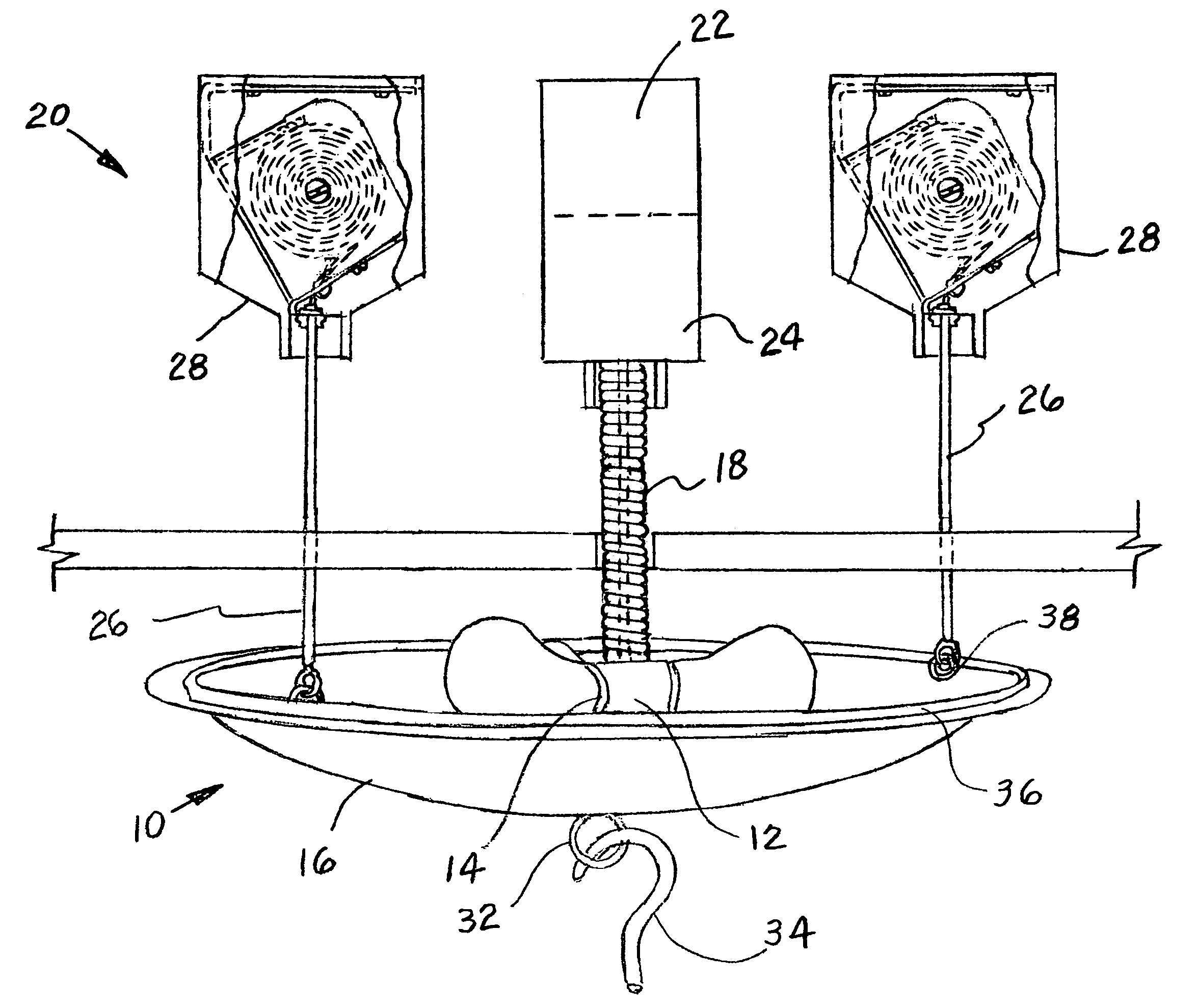
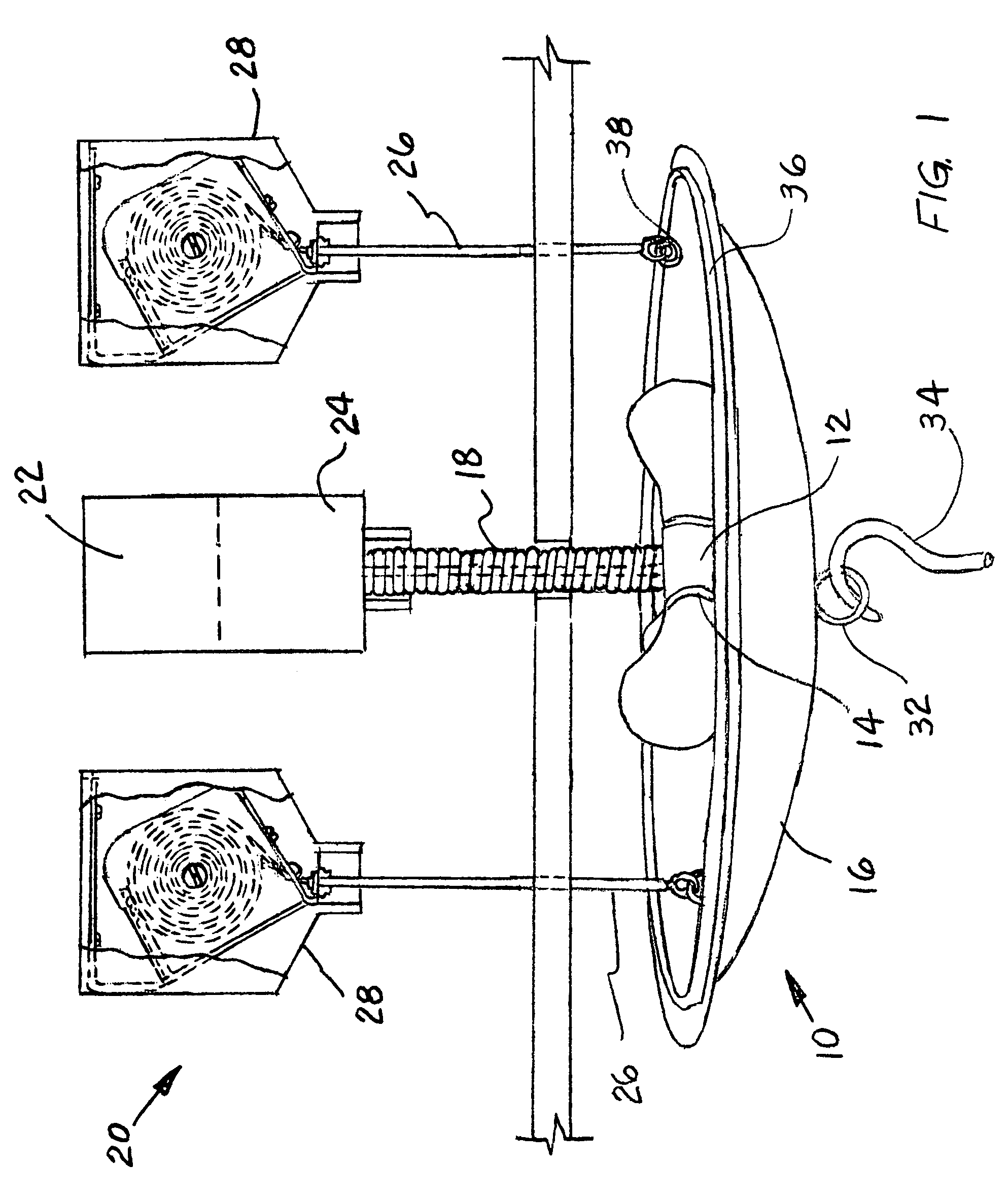
[0011]FIG. 1 is a side cut-away view of a pull down light fixture showing the elements hidden within a ceiling and a hook member engageable with a pull down attachment of the present invention; and

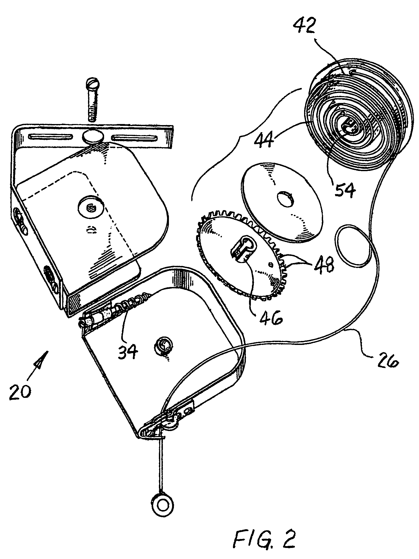
[0012]FIG. 2 is an exploded perspective view of a retraction cord means used to lower and raise the pull down light fixture of the present invention.

DETAILED DESCRIPTION OF A PRESENTLY PREFERRED AND VARIOUS ALTERNATIVE EMBODIMENTS OF THE INVENTION

[0013]Prior to proceeding to the more detailed description of the present invention it should be noted that, for the sake of clarity and understanding, identical components which have identical functions have been identified with identical reference numerals throughout the several views illustrated in the drawing figures.

[0014]Reference is now made, more particularly, to drawing FIGS. 1 and 2...


PUM


Abstract

A pull down light fixture having a cover connected to a bottom portion of the light fixture. A power source is connected to the light fixture via a power cord. A power cord base engages a ceiling for housing the power cord. A predetermined plurality of retraction cords are connected to the cover for at least one of raising and lowering the cover. A retraction cord mechanism is connected to each retraction cord for enabling such retraction cords to at least one of extend and retract. A predetermined plurality of retraction cord bases engage the ceiling for housing each retraction cord and retraction cord mechanism. A pull down attachment is connected to the light fixture for enabling the light fixture to be pulled down.

Description

CROSS REFERENCE TO RELATED APPLICATION[0001]This application is closely related to and claims priority from U.S. Provisional Patent Application Ser. No. 60 / 772,960 filed on Feb. 14, 2006, and its teachings are incorporated into the present document by reference thereto.FIELD OF THE INVENTION[0002]The present invention relates, in general, to light fixtures and, more particularly, the invention relates to a light fixture on a ceiling of any height in which the light fixture can be manually lowered and raised a predetermined distance from the ceiling.BACKGROUND OF THE INVENTION[0003]Prior to the conception and development of the present invention, as is generally well known in the prior art, light bulbs are used in practically every room of a home or office and must be replaced every so often. Climbing up a ladder or balancing on a chair to change burned out bulbs in a high ceiling fixture can be quite difficult and dangerous for anyone, even possibly resulting in injury to those invo...

Claims


Application Information

Patent Timeline
Patent Type & Authority Patents(United States)
IPC IPC(8): F21V21/16
CPCF21S8/06F21V21/104F21V21/38F21V27/00
Inventor ROGERS, ELIZABETH M.
Owner ROGERS TRUSTEE ELIZABETH MAYS
Why Eureka
Try Eureka