Counterbalance apparatus

a counterbalance and workstation technology, applied in the field of counterbalance apparatus, can solve the problems of load on the work surface being out of balance, and achieve the effects of easy raising and lowering the work surface of the workstation, small force, and easy lifting and lowering of the workstation

Inactive Publication Date: 2011-03-03
LONG DENNIS
View PDF14 Cites 10 Cited by
  • Summary
  • Abstract
  • Description
  • Claims
  • Application Information

AI Technical Summary

Benefits of technology

[0006]A counterbalance apparatus for use in a workstation to raise and lower a work surface of the workstation. The counterbalance apparatus enables a user to easily raise and lower the work surface of the workstation by applying a small upward or downward force on the work surface. The counterbalance apparatus compensates for the load on the work surface so that a relatively small force can be used to raise or lower the work surface. The force necessary to move the work surface up and down is substantially constant for all loads throughout the vertical travel of the work surface. The counterbalance apparatus includes an inner column telescopingly mounted in an outer column. A base member is positioned at one end of the outer column. A grooved member is positioned between the inner column and the base member and a force mechanism is positioned between the grooved member and the inner column or the work surface. The grooved member has first grooves which are non-linear and second grooves which are linear. The first grooves engage first rollers in the inner column. The second grooves engage second rollers in the base member. As the work surface is raised and lowered, the rollers move along the grooves and the grooved member moves in and out of the base member and the inner column. As the groove member slides in and out of the base member and the inner column, the grooved member rotates. The movement of the rollers in the grooves compensates for the additional compression force of the force mechanism to enable the work surface to be easily raised and lowered with minimal force from the user.

Problems solved by technology

The load on the work surface is out-of-balance when there is too much load or not enough load on the work surface based on the preload setting of the counterbalance apparatus.

Method used


Image

  • Counterbalance apparatus
  • Counterbalance apparatus
  • Counterbalance apparatus

Examples


Embodiment Construction

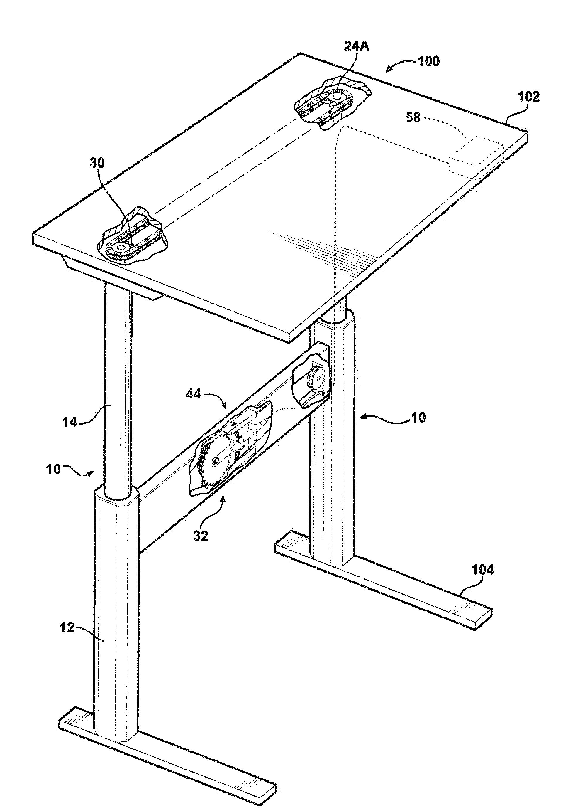
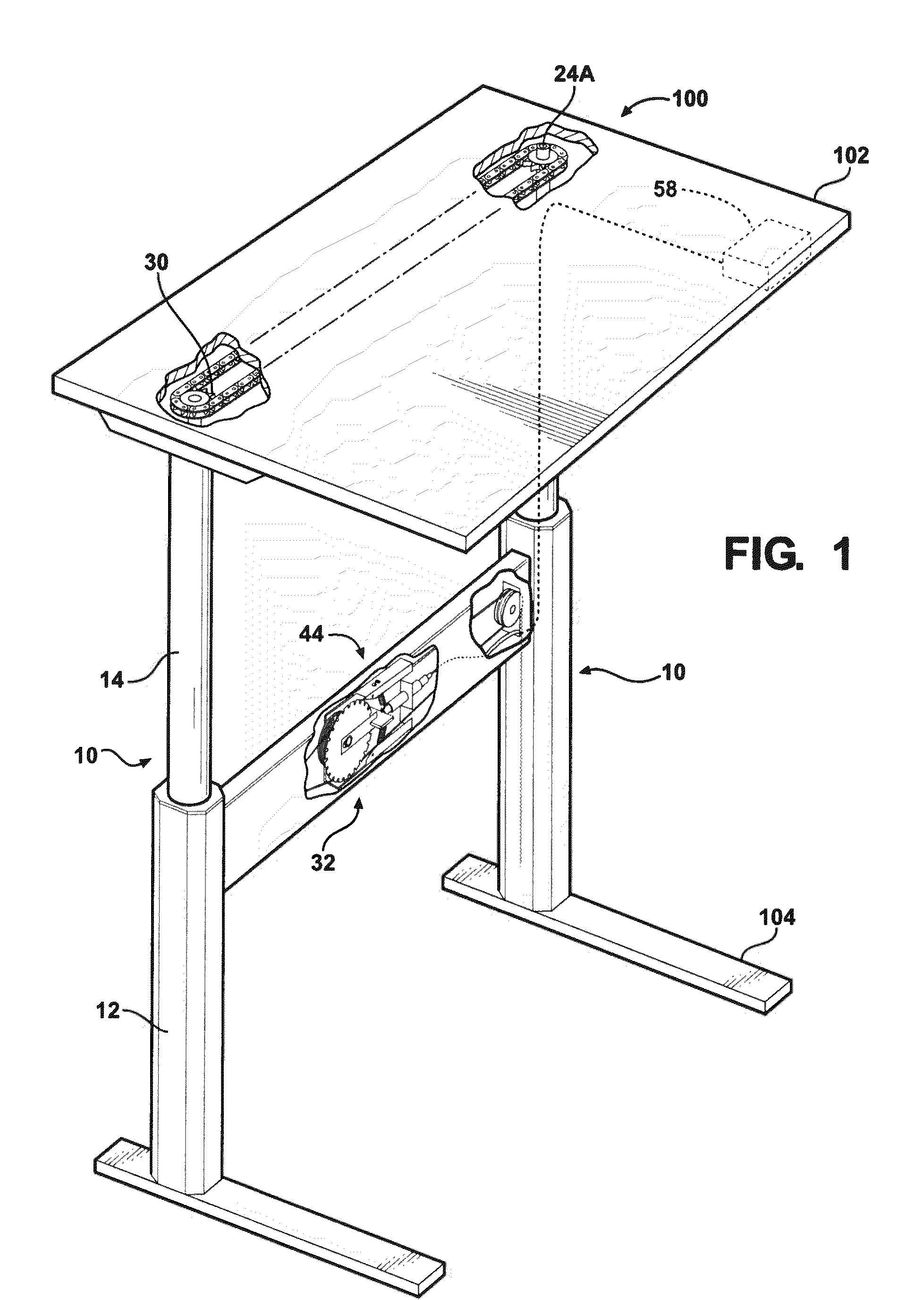
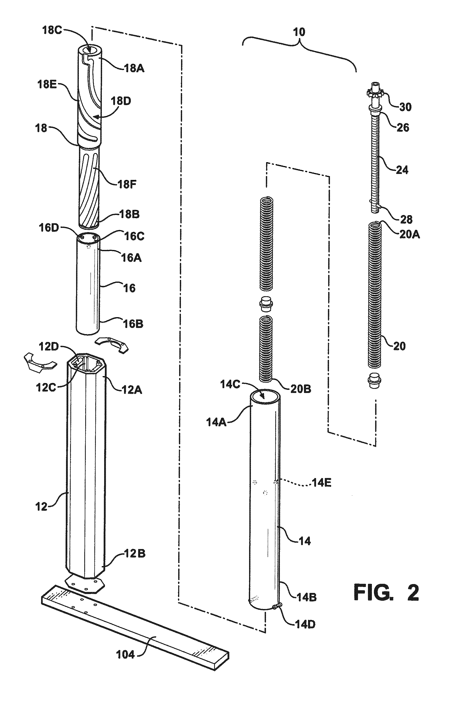
[0023]FIGS. 1 to 6 show the counterbalance apparatus 10 of the present invention. In one (1) embodiment, the counterbalance apparatus 10 is for use in a workstation 100 to raise and lower a work surface 102 of a workstation 100. The counterbalance apparatus 10 enables a user to easily raise and lower the work surface 102 of a workstation 100 by applying a small upward or downward force on the work surface 102 even when there is a load on the work surface 102. The counterbalance apparatus 10 is positioned between the work surface 102 and the base 104 of the workstation 100. In one (1) embodiment, the counterbalance apparatus 10 is housed in the leg of the workstation 100. In one (1) embodiment, the workstation 100 includes a pair of counterbalance apparatus 10 which work together to raise or lower the work surface 102 (FIG. 1). In another embodiment, the workstation 150 has a single counterbalance apparatus 10 such as in a pedestal table (FIG. 6). However, it is understood that the w...


PUM


Abstract

A counterbalance apparatus for use in a workstation to raise and lower a work surface of the workstation. The counterbalance apparatus compensates for the load on the work surface. The counterbalance apparatus includes an inner column telescopingly mounted in an outer column. A base member is positioned at one end of the outer column. A grooved member positioned between the inner column and the base member and a force mechanism between the grooved member and the inner column or the work surface. The grooved member moves in and out of the inner column and base member to raise and lower the work surface.

Description

CROSS REFERENCES TO RELATED APPLICATIONS[0001]Not ApplicableSTATEMENT REGARDING FEDERALLY SPONSORED RESEARCH OR DEVELOPMENT[0002]Not ApplicableBACKGROUND OF THE INVENTION[0003](1) Field of the Invention[0004]The present invention relates to a counterbalance apparatus for use in moving a work surface. In particular, the present invention relates to a counterbalance apparatus for vertically moving the work surface of a workstation where the counterbalance apparatus exerts a substantially constant force on the moving work surface throughout the entire vertical travel of the work surface.[0005]There remains a need for a counterbalance apparatus which is durable and easy to construct and which allows for easily raising and lowering a work surface and which can be mounted in the leg of a workstation.BRIEF SUMMARY OF THE INVENTION[0006]A counterbalance apparatus for use in a workstation to raise and lower a work surface of the workstation. The counterbalance apparatus enables a user to eas...

Claims


Application Information

Patent Timeline
Patent Type & Authority Applications(United States)
IPC IPC(8): A47B9/02F16M11/26A47B9/20
CPCA47B9/02
Inventor LONG, DENNIS L.
Owner LONG DENNIS
Why Eureka
Try Eureka