Rotary impact tool

a rotary and tool technology, applied in the field of rotary impact tools, can solve the problems of increased impact force, difficult to determine the timing of tightening, and difficulty in setting the proper number of impacts

Active Publication Date: 2014-03-25
MAKITA CORP
View PDF27 Cites 73 Cited by
  • Summary
  • Abstract
  • Description
  • Claims
  • Application Information

AI Technical Summary

Benefits of technology

[0009]Therefore, even in the case that, for example, a screw or the like is being tightened at the normal speed (high speed), the rotational speed of the motor is switched to the low speed once start of the impact is detected. As a result, the impact force of the hammer with respect to the anvil is reduced, and the interval between impacts is made relatively long.
[0010]That is, even in the case that a screw or the like is being tightened at a high speed, the impact force can be made relatively small, and the interval between impacts can be made relatively long. Therefore, it is easy to determine the tightening timing based on the judgment by the operator, and no unintended excessive impact operation occurs, so that it is possible to preventing a trouble such as screw decapitation.
[0011]Further, since a screw or the like can be tightened at a high speed, it is possible to prevent deterioration in work efficiency.
[0015]That is even in the case that the motor is switched to the low speed, it is possible to adjust the rotational speed of the motor, so that it is easy to adjust the interval between impacts.
[0018]As a result, a screw or the like can be loosened quickly.

Problems solved by technology

Thus, it is difficult to set a proper number of impacts; further, since the rotation of the hammer is at high speed, the impact force is also increased.
This may lead to decapitation or the like, in which the head of the tex screw 3 is torn off.
Further, in the case that the tightening completing timing (motor stopping timing) is determined based on the judgment by the operator regardless of the number of impacts, it is difficult to determine the tightening completing timing if the interval between the impacts is very short, and unintended impacts are applied, decapitation or the like, in which the head of the tex screw 3 is torn off, is likely to be caused.

Method used


Image

  • Rotary impact tool
  • Rotary impact tool
  • Rotary impact tool

Examples


embodiment 1

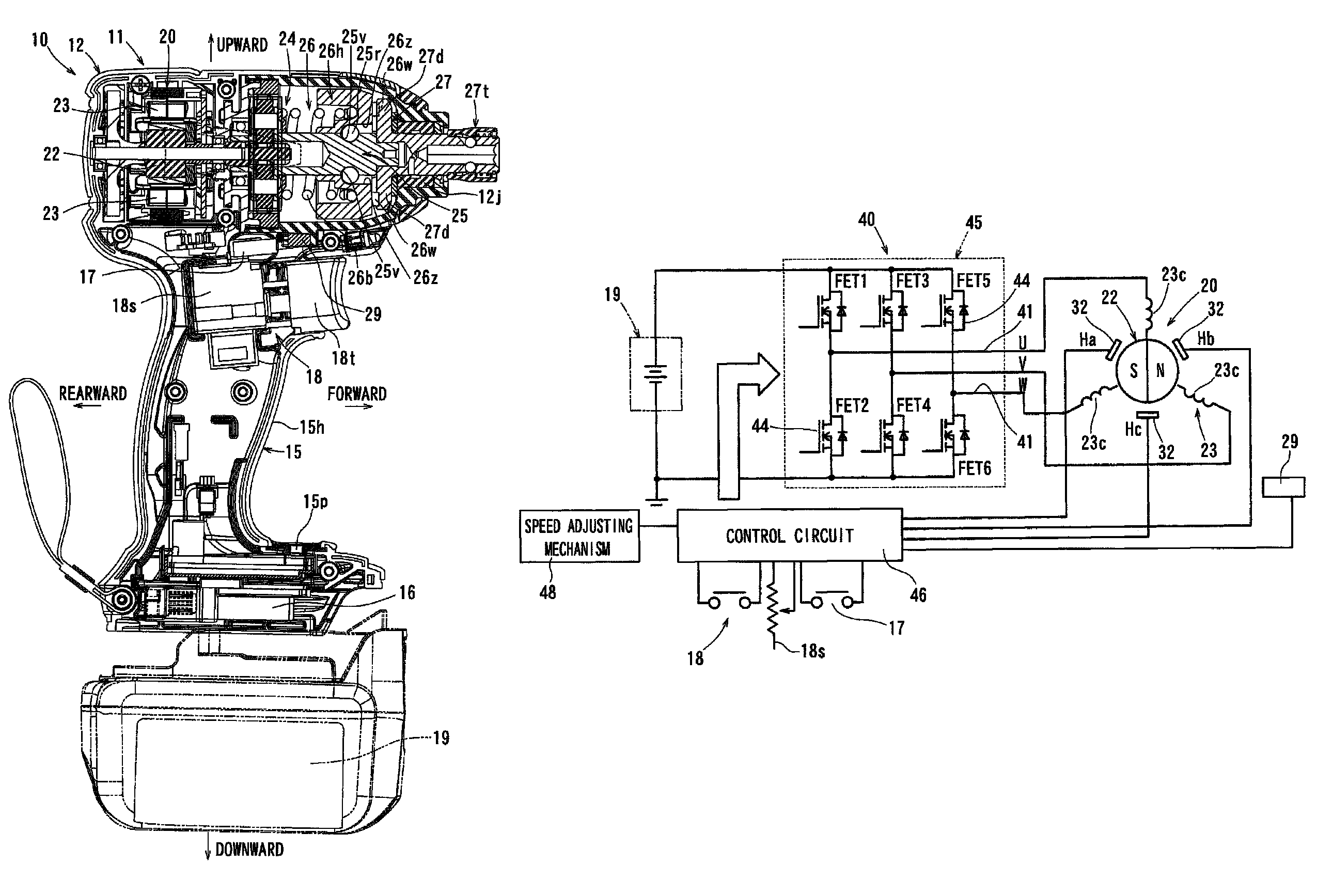
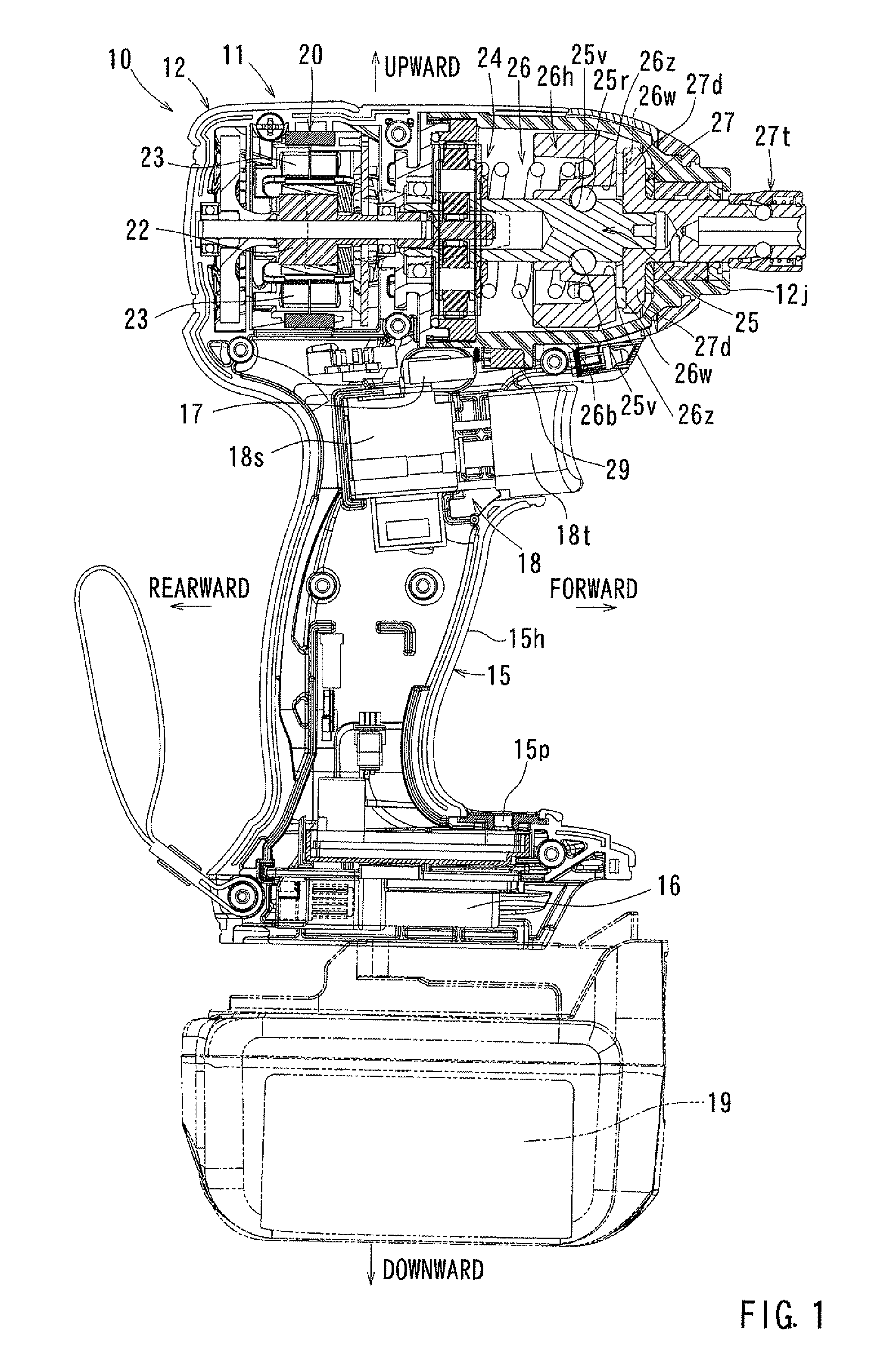
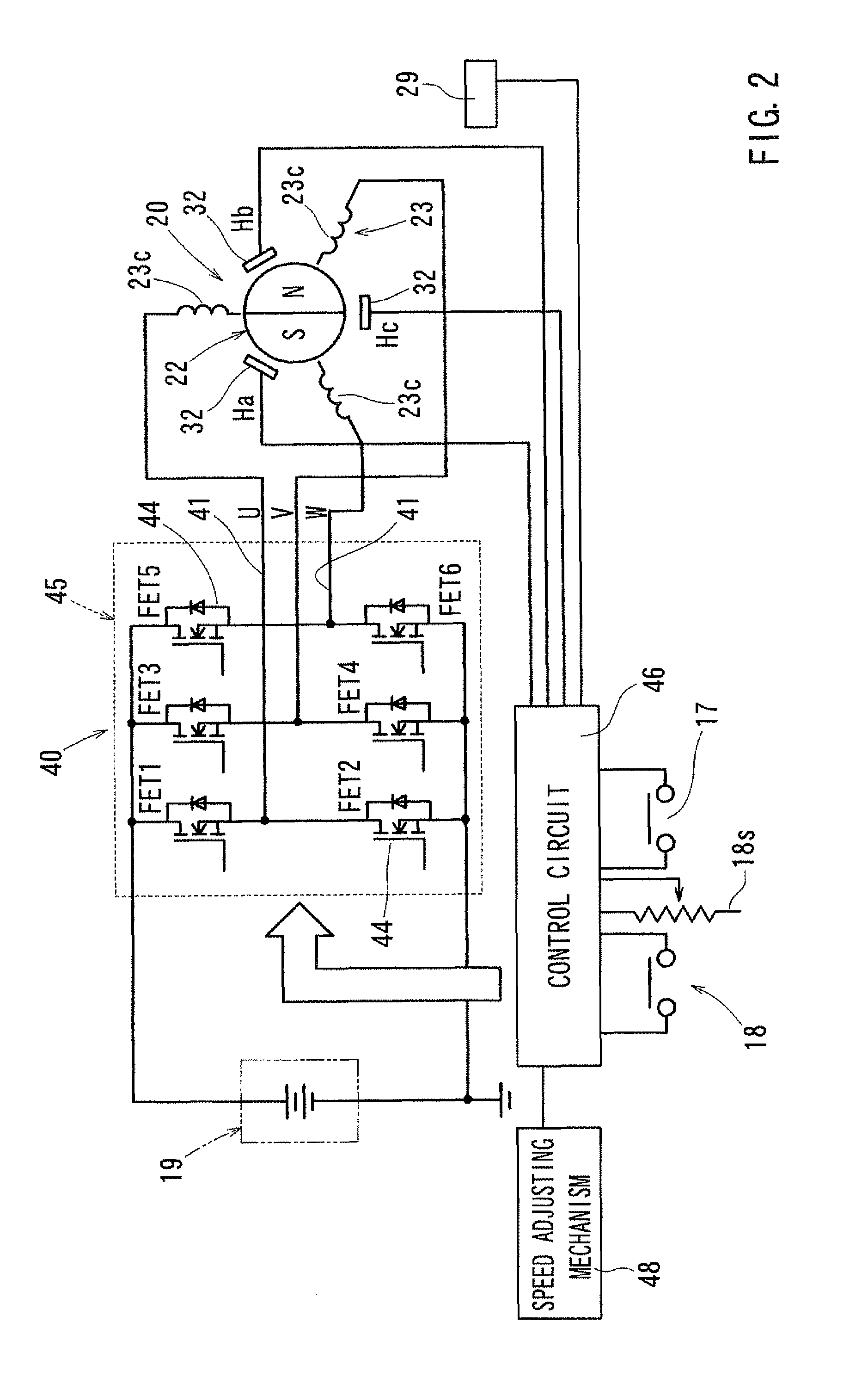
[0024]In the following, a rotary impact tool according to Embodiment 1 of the present invention will be described with reference to FIGS. 1 through 5. The rotary impact tool of the present embodiment is an impact driver (hereinafter referred to as rotary impact tool) using a DC brushless motor as a drive source.

[0025]Here, forward, rearward, rightward, and leftward indicated in the drawings correspond to forward, rearward, rightward, and leftward with respect to the rotary impact tool.

Outline of the Rotary Impact Tool

[0026]As shown in FIG. 1, a housing 11 of a rotary impact tool 10 according to the present embodiment is constituted by a tubular housing main body 12, and a grip portion 15 formed so as to protrude from a lateral portion (lower portion in FIG. 1) of the housing main body 12.

[0027]The housing main body 12 coaxially accommodates a DC brushless motor 20, a planetary gear mechanism 24, a spindle 25, an impact force generation mechanism 26, and an anvil 27 in this order fro...


PUM


Abstract

A rotary impact tool includes: a hammer rotating by receiving a rotational force of a motor; an anvil rotating by receiving a rotational force of the hammer; and an end tool attached to the anvil, the rotary impact tool being constructed such that when a torque of a value not less than a predetermined value is applied to the anvil from the outside, the hammer is disengaged from the anvil to rotate idle and applies an impact to the anvil in a rotational direction after rotating idle by a predetermined angle, the rotary impact tool including an impact detector configured to detect impacts and a speed switching device configured to switch the rotational speed of the motor, and when the impact detector detects an impact during rotation of the anvil in a tightening direction, the speed switching device switches the rotational speed of the motor from a normal speed to a low speed.

Description

TECHNICAL FIELD[0001]The present invention relates to a rotary impact tool that has a hammer rotating by receiving the rotational force of a motor, an anvil rotating by receiving the rotational force of the hammer, and an end tool attached to the anvil and is constituted such that when a torque of a value not less than a predetermined value is applied to the anvil from the outside, the hammer is detached from the anvil to rotate idle and applies an impact to the anvil in the rotational direction after rotating idle by a predetermined angle.BACKGROUND ART[0002]A pertinent conventional rotary impact tool is disclosed in Japanese Laid-Open Patent Publication No. 2001-260042 (Japanese Patent No. 3670189).[0003]The rotary impact tool disclosed in this publication is an impact driver, which is configured to allow setting of the number of times that the hammer apply impacts to the anvil so that a number of screws or the like can be tightened with the same torque. More specifically, the imp...

Claims


Application Information

Patent Timeline
Patent Type & Authority Patents(United States)
IPC IPC(8): B25B21/02
CPCB25B21/02B25B21/026B25B23/147B25B21/008B25B23/14
Inventor MATSUNAGA, YUTAKAYAMAMOTO, HIROKATSUHAYASHI, KATSUNAICHIKAWA, YOSHITAKA
Owner MAKITA CORP
Why Eureka
Try Eureka