
Flexible vascular occluding device

a flexible, vascular occluding technology, applied in the field of implantable devices, can solve problems such as thin walls and injury, and achieve the effect of easy conformation and easy navigation of tortuous vessels

Active Publication Date: 2013-12-31
TYCO HEALTHCARE GRP LP
View PDF573 Cites 77 Cited by
  • Summary
  • Abstract
  • Description
  • Claims
  • Application Information

AI Technical Summary

Benefits of technology

[0015]An aspect of the present invention provides a highly flexible implantable occluding device that can easily navigate the tortuous vessels of the neurovasculature. Additionally, occluding device can easily conform to the shape of the tortuous vessels of the vasculature. Furthermore, the occluding device can direct the blood flow within a vessel away from an aneurysm; additionally such an occluding device allows adequate blood flow to be provided to adjacent structures such that those structures, whether they are branch vessels or oxygen demanding tissues, are not deprived of the necessary blood flow.
[0017]The occluding device is flexible enough to closely approximate the native vasculature and conform to the natural tortuous path of the native blood vessels. One of the significant attributes of the occluding device according to the present invention is its ability to flex and bend, thereby assuming the shape of a vasculature within the brain. These characteristics are for a neurovascular occluding device than compared to a coronary stent, as the vasculature in the brain is smaller and more tortuous.
[0018]In general terms, aspects of the present invention relate to methods and devices for treating aneurysms. In particular, a method of treating an aneurysm with a neck comprises deploying a vascular occluding device in the lumen of a vessel at the location of the aneurysm, whereby the blood flow is redirected away from the neck of the aneurysm. The induced stagnation of the blood in the lumen of the aneurysm would create embolization in the aneurysm. The occluding device spans the width of the stem of the aneurysm such that it obstructs or minimizes the blood flow to the aneurysm. The occluding device is very flexible in both its material and its arrangement. As a result, the occluding device can be easily navigated through the tortuous blood vessels, particularly those in the brain. Because the occluding device is flexible, very little force is required to deflect the occluding device to navigate through the vessels of the neurovasculature, which is of significance to the operating surgeon.
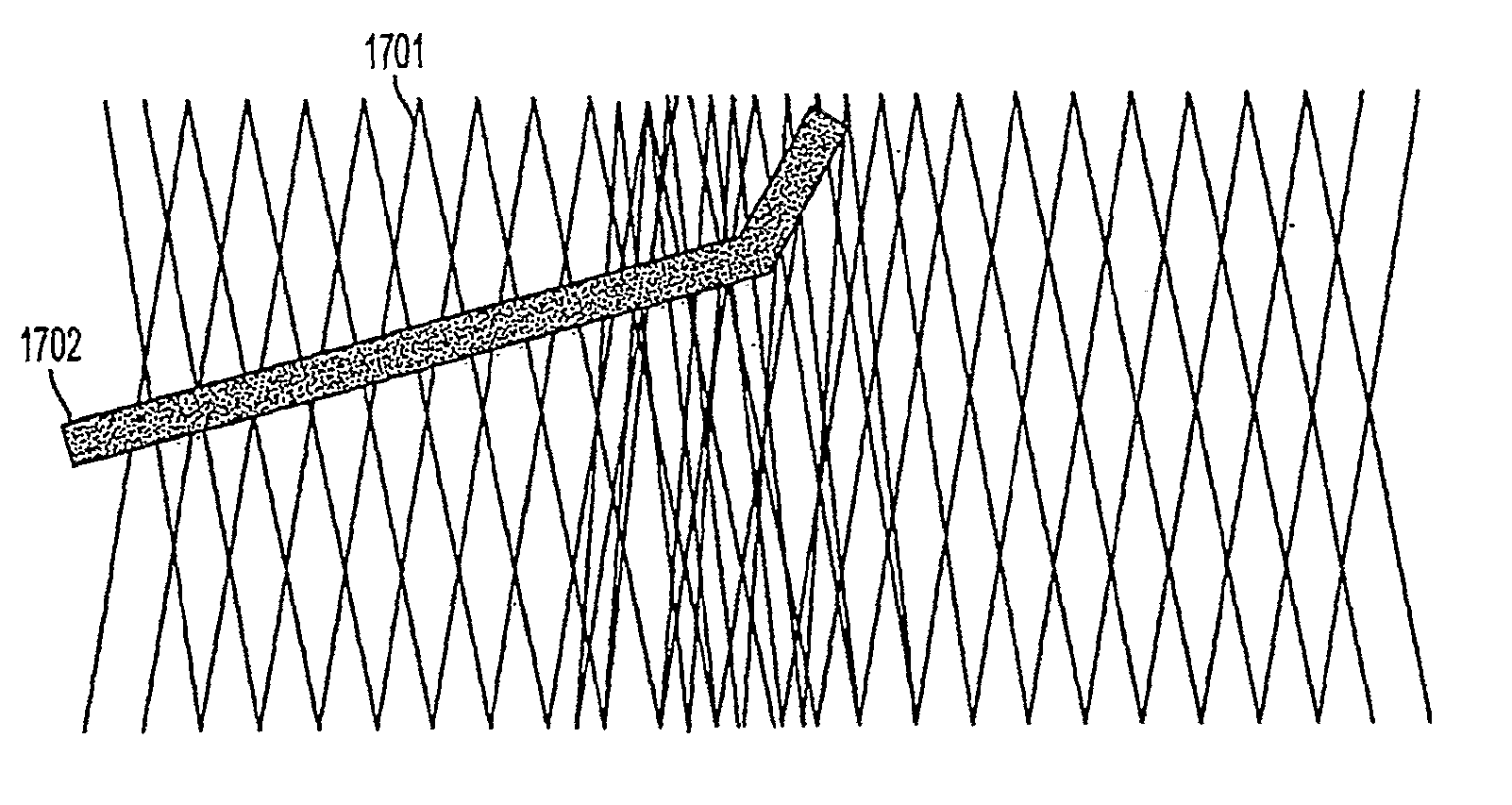
[0019]A feature of the occluding device, apart from its flexibility, is that the occluding device may have an asymmetrical braid pattern with a higher concentration of braid strands or a different size of braid strands on the surface facing the neck of the aneurysm compared to the surface radially opposite to it. In one embodiment, the surface facing the aneurysm is almost impermeable and the diametrically opposed surface is highly permeable. Such a construction would direct blood flow away from the aneurysm, but maintain blood flow to the side branches of the main vessel in which the occluding device is deployed.
[0020]In another embodiment, the occluding device has an asymmetrical braid count along the longitudinal axis of the occluding device. This provides the occluding device with a natural tendency to curve, and hence conform to the curved blood vessel. This reduces the stress exerted by the occluding device on the vessel wall and thereby minimizing the chances of aneurysm rupture. Additionally, because the occluding device is naturally curved, this eliminates the need for the tip of the micro-catheter to be curved. Now, when the curved occluding device is loaded on to the tip of the micro-catheter, the tip takes the curved shape of the occluding device. The occluding device could be pre-mounted inside the micro-catheter and can be delivered using a plunger, which will push the occluding device out of the micro-catheter when desired. The occluding device could be placed inside the micro-catheter in a compressed state. Upon exiting the micro-catheter, it could expand to the size of the available lumen and maintain patency of the lumen and allow blood flow through the lumen. The occluding device could have a lattice structure and the size of the openings in the lattice could vary along the length of the occluding device. The size of the lattice openings can be controlled by the braid count used to construct the lattice.
[0024]In another embodiment, a device with a braided structure is made in order to conform to a curved vessel in the body, where the density of the braid provides enough rigidity and radial strength. Additionally, the device can be compressed using a force less than 10 grams. This enables the device to be compliant with the artery as the arterial wall is pulsating. Also, the device is capable of bending upon applying a force of less than 5 gram / cm.

Problems solved by technology

In this instance, some blood is still allowed to reach the aneurysm, but not enough to create a laminar flow within the aneurysm that would cause injury to its thinned walls.

Method used


Image

  • Flexible vascular occluding device
  • Flexible vascular occluding device
  • Flexible vascular occluding device

Examples


Embodiment Construction

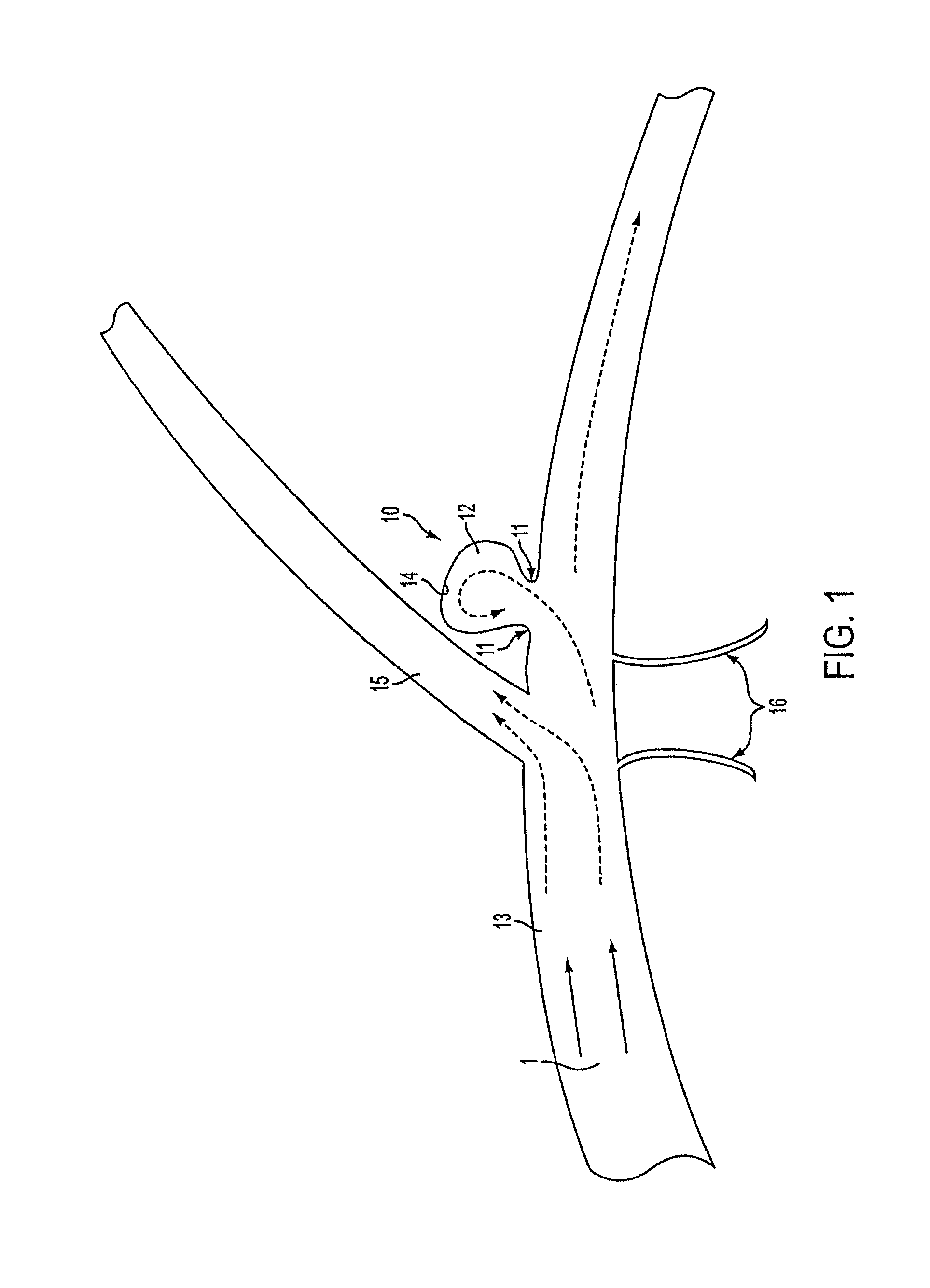
[0046]The devices shown in the accompanying drawings are intended for treating aneurysms. They are generally deployed, using micro-catheters, at the location of a cerebral aneurysm that is intended to be treated. One such system is disclosed in copending U.S. Patent Application titled “System and Method for Delivering and Deploying an Occluding Device Within a Vessel”, U.S. Ser. No. 11 / 136,398, filed on May 25, 2005, which is incorporated herein by reference in its entirety. The embodiments of the endovascular occluding device according to aspects of the present invention is useful for treating cerebral aneurysms that are commonly treated using surgical clips, microcoils or other embolic devices.

[0047]FIG. 1 illustrates a typical cerebral aneurysm 10 in the brain. A neck 11 of the aneurysm 10 can typically define an opening of between about 2 to 25 mm. As is understood, the neck 11 connects the vessel 13 to the lumen 12 of the aneurysm 10. As can be seen in FIG. 1, the blood flow 1 ...


PUM


Abstract

A vascular occluding device for modifying blood flow in a vessel, while maintaining blood flow to the surrounding tissue. The occluding device includes a flexible, easily compressible and bendable occluding device that is particularly suited for treating aneurysms in the brain. The neurovascular occluding device can be deployed using a micro-catheter. The occluding device can be formed by braiding wires in a helical fashion and can have varying lattice densities along the length of the occluding device. The occluding device could also have different lattice densities for surfaces on the same radial plane.

Description

FIELD OF THE INVENTION[0001]The invention relates generally to an implantable device that could be used in the vasculature to treat common vascular malformations. More particularly, it relates to a flexible, biocompatible device that can be introduced into the vasculature of a patient to embolize and occlude aneurysms, particularly cerebral aneurysms.BACKGROUND OF THE INVENTION[0002]Walls of the vasculature, particularly arterial walls, may develop pathological dilatation called an aneurysm. Aneurysms are commonly observed as a ballooning-out of the wall of an artery. This is a result of the vessel wall being weakened by disease, injury or a congenital abnormality. Aneurysms have thin, weak walls and have a tendency to rupture and are often caused or made worse by high blood pressure. Aneurysms could be found in different parts of the body; the most common being abdominal aortic aneurysms (AAA) and the brain or cerebral aneurysms. The mere presence of an aneurysm is not always life-...

Claims


Application Information

Patent Timeline
Patent Type & Authority Patents(United States)
IPC IPC(8): A61B17/12A61F2/90A61F2/06A61F2/82
CPCA61B2017/1205A61B17/12022A61B17/12118A61F2002/823A61F2/90
Inventor GARCIA, ADRIANYE, TING TINATRAN, QUANG QBEREZ, AARON L.
Owner TYCO HEALTHCARE GRP LP
Learn More