Flying vehicle

a technology of flying vehicles and aircraft, applied in the field of flying vehicles, can solve the problems of insufficient development and realization of aerial transportation means, no adequate means to replace conventional airplanes for human transportation, environmental problems, etc., and achieve the effects of little noise, little vibration, and little abrasion

Inactive Publication Date: 2017-12-21
CHOI KIHYOUN +1
View PDF4 Cites 11 Cited by
  • Summary
  • Abstract
  • Description
  • Claims
  • Application Information

AI Technical Summary

Benefits of technology

[0024]In accordance with the present disclosure, by using the magnets for rotation of the blades, there is no need for a motor directly driving the blades, and therefore a rotating shaft. Thus, the flying vehicle is lightweight, generates little noise and little vibration and has little abrasion, and has excellent durability.
[0025]According to the present disclosure, there is an advantage that the flying vehicle can be easily raised, lowered and changed in direction.
[0026]According to the present disclosure, there is an advantage that the flying vehicle can be operated environmentally.

Problems solved by technology

However, the development and realization of the aerial transportation means are insufficient.
However, there is no adequate means to replace conventional airplanes for human transport.
Conventional airplanes use fossil fuels such as aviation oil and thus cause environmental problems due to air pollution.
Further, there is a problem that noise and vibration are accompanied by use of the engine.
However, in the above-described prior art, air is sucked from below the lower body by the main fan and then discharged back toward below the lower body, so that it is difficult to achieve actual flight.
Further, since the rotation of the blades is accomplished by a power source converted by a solar module, it is difficult to operate at night without the sun shining.
Further, since the rotation of the blades for flight is realized by the driving of the motor, there is a problem in that the load on the rotation shaft is large and the durability thereof is degraded.

Method used


Image

  • Flying vehicle
  • Flying vehicle
  • Flying vehicle

Examples


Embodiment Construction

[0040]Examples of various embodiments are illustrated and described further below. It will be understood that the description herein is not intended to limit the claims to the specific embodiments described. On the contrary, it is intended to cover alternatives, modifications, and equivalents as may be included within the spirit and scope of the present disclosure as defined by the appended claims.

[0041]It will be understood that, although the terms “first”, “second”, “third”, and so on may be used herein to describe various elements, components, regions, layers and / or sections, these elements, components, regions, layers and / or sections should not be limited by these terms. These terms are used to distinguish one element, component, region, layer or section from another element, component, region, layer or section. Thus, a first element, component, region, layer or section described below could be termed a second element, component, region, layer or section, without departing from ...


PUM


Abstract

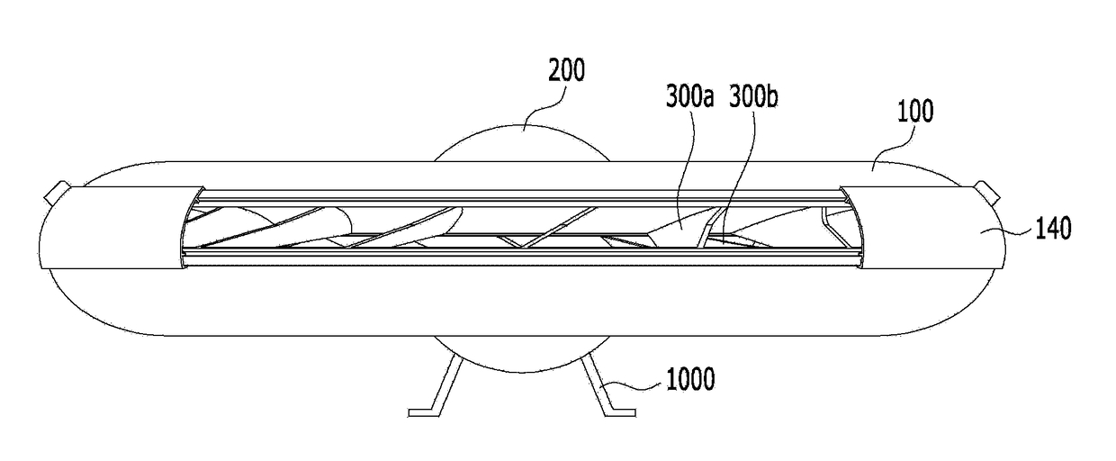
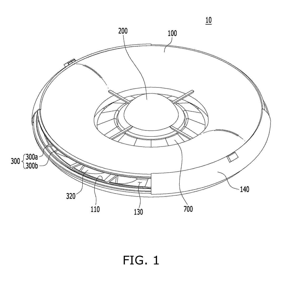
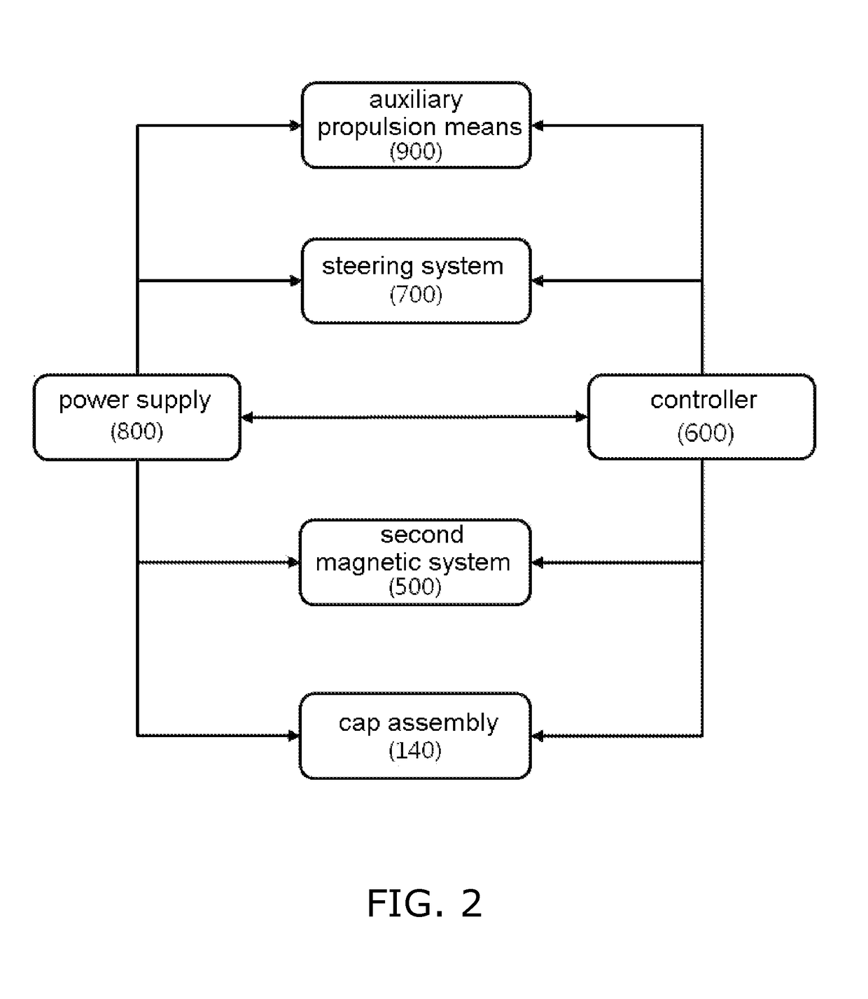
The present disclosure relates to a flying vehicle comprising an annular hollow outer body having an outer circumferential open portion and an inner circumferential open portion; a blade system disposed in the outer body and configured to allow air flow from the outer circumferential open portion to the inner circumferential open portion; a first magnetic system configured to enable the blade system to be kept to have a clearance with the annular hollow outer body and to be kept in a floated state using a first magnetic force; a second magnetic system configured to allow the blade system to rotate using a second magnetic force; and a steering system configured to allow air discharged from the inner circumferential open portion via the blade system to flow upwardly or downwardly.

Description

CROSS-REFERENCE TO RELATED APPLICATION[0001]This application claims the benefit of Korean patent application No. 10-2016-0074666 filed on Jun. 15, 2016, the entire content of which is incorporated herein by reference for all purposes as if fully set forth herein.BACKGROUNDField of the Present Disclosure[0002]The present disclosure relates to a flying vehicle. In particular, the present disclosure relates to a flying vehicle comprising an annular hollow outer body having an outer circumferential open portion and an inner circumferential open portion; a blade system disposed in the outer body and configured to allow air flow from the outer circumferential open portion to the inner circumferential open portion; a first magnetic system configured to enable the blade system to be kept to have a clearance with the annular hollow outer body and to be kept in a floated state using a first magnetic force; a second magnetic system configured to allow the blade system to rotate using a second ...

Claims


Application Information

Patent Timeline
Patent Type & Authority Applications(United States)
IPC IPC(8): B64C39/06B64D27/24B64C27/08
CPCB64C39/064B64D27/24B64C27/08B64C21/025B64C27/20B64C39/06B64U10/13B64U50/19B64U50/14B64C39/003Y02T50/40Y02T50/60B64C15/02B64C39/024B64D27/20B64D33/08B64D1/00B64U10/00B64U50/12B64U30/00
Inventor CHOI, KIHYOUNCHOI, SOYEON
Owner CHOI KIHYOUN
Why Eureka
Try Eureka