
Electric power steering system

a technology of electric power steering and steering column, which is applied in the direction of bearing unit rigid support, couplings, gearing, etc., can solve the problems of increasing backlash, laborious work and boosting up production costs, and teeth-hitting sound, so as to reduce the amount of backlash, suppress the drop in the durability of the first urging member, and reduce the noise of teeth-hitting sound.

Inactive Publication Date: 2006-08-03
JTEKT CORP
View PDF4 Cites 26 Cited by
  • Summary
  • Abstract
  • Description
  • Claims
  • Application Information

AI Technical Summary

Benefits of technology

[0012] This invention was accomplished in view of the above problems and its object is to provide an electric power steering system which produces little noise, features excellent durability and permits the torque to fluctuate little.
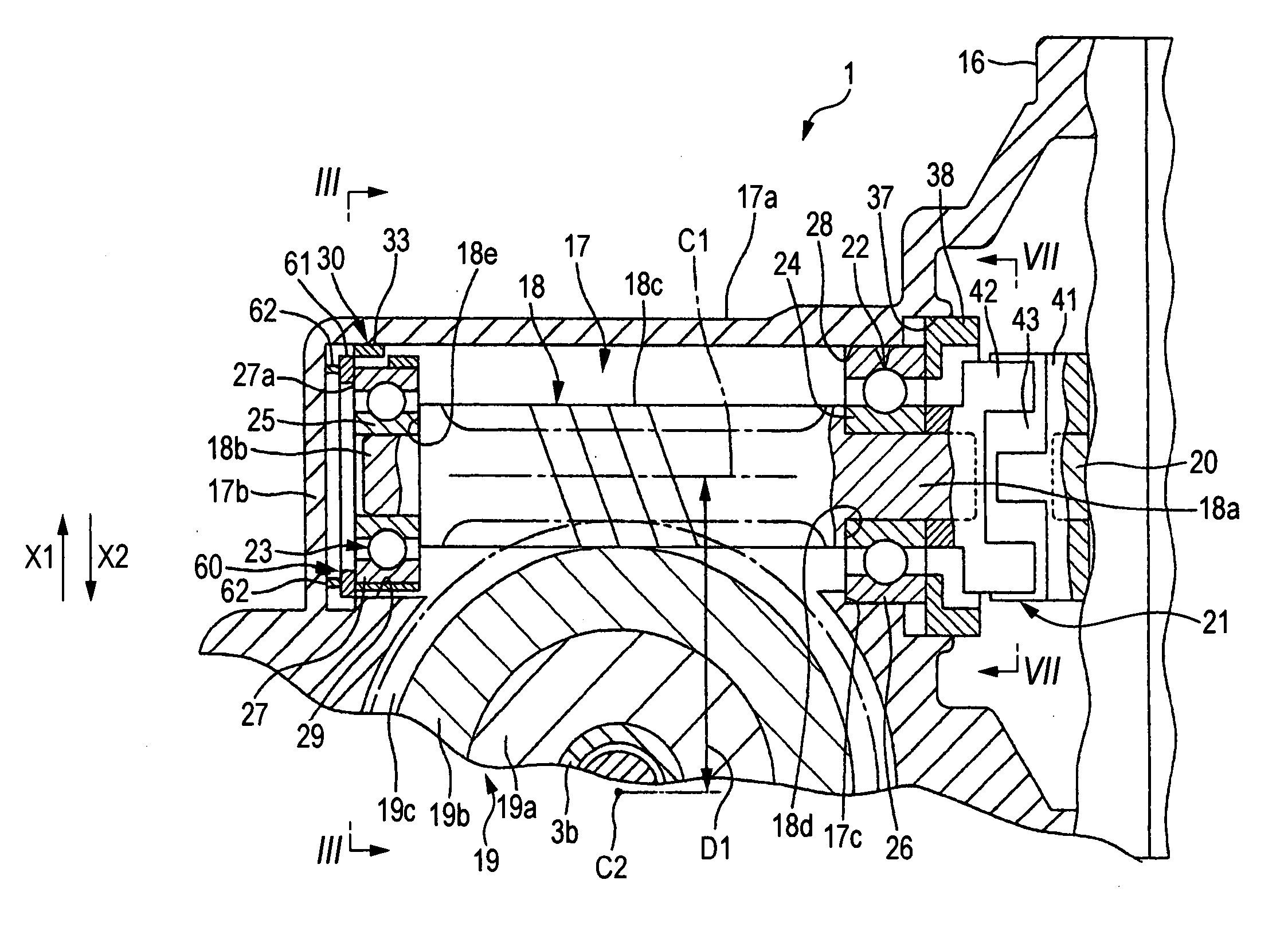
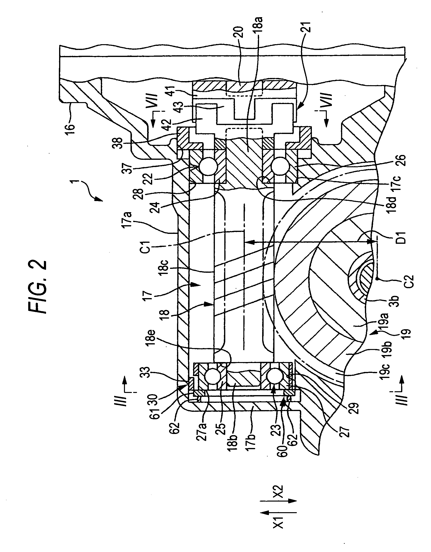
[0026] In this invention, the drive gear is urged in a direction in which the distance is shorted between the centers to decrease the amount of backlash in a portion where the drive gear meshes the driven gear. As a result, noise due to teeth-hitting sound can be decreased. Further, rattling of the drive gear in the axial direction is suppressed by the second urging member thereby to suppress the first urging member from rattling in the axial direction of the drive gear. It is therefore made possible to suppress a drop in the durability of the first urging member caused by rattling of the first urging member and to suppress the generation of noise caused by the hitting sound. Further, a fluctuation in the rotational torque of the drive gear can be suppressed.

Problems solved by technology

When, for example, traveling on a rough road, however, there may generate teeth-hitting sound (rattling sound) due to the backlash reversely input from the road surface.
In assembling the worm shaft and the worm wheel, so far, it is a practice to select the individual parts depending upon the degree of dispersion in the dimensional precision and assemble those which assume suitable degrees of precision when combined together (so-called matching assembly) requiring, however, very laborious work and boosting up the cost of production.
Further, even if the backlash may, at first, have been set in a suitable range owing to the matching assembly, the backlash increases due to wear of the teeth after aging producing abnormal sound.
According to the former publication, however, the curved leaf spring often rattles due to the clearance in a direction other than the urging direction.
There further remain problems in that sliding sound or hitting sound is generated between the worm shaft and the worm wheel, or hitting noise is generated between the curved leaf spring and the housing.
Therefore, the structure of the cam mechanism tends to become complex and the operation tends to lose stability.

Method used


Image

  • Electric power steering system
  • Electric power steering system
  • Electric power steering system

Examples


Embodiment Construction

[0040] Preferred embodiments of the invention will now be described with reference to the accompanying drawings.

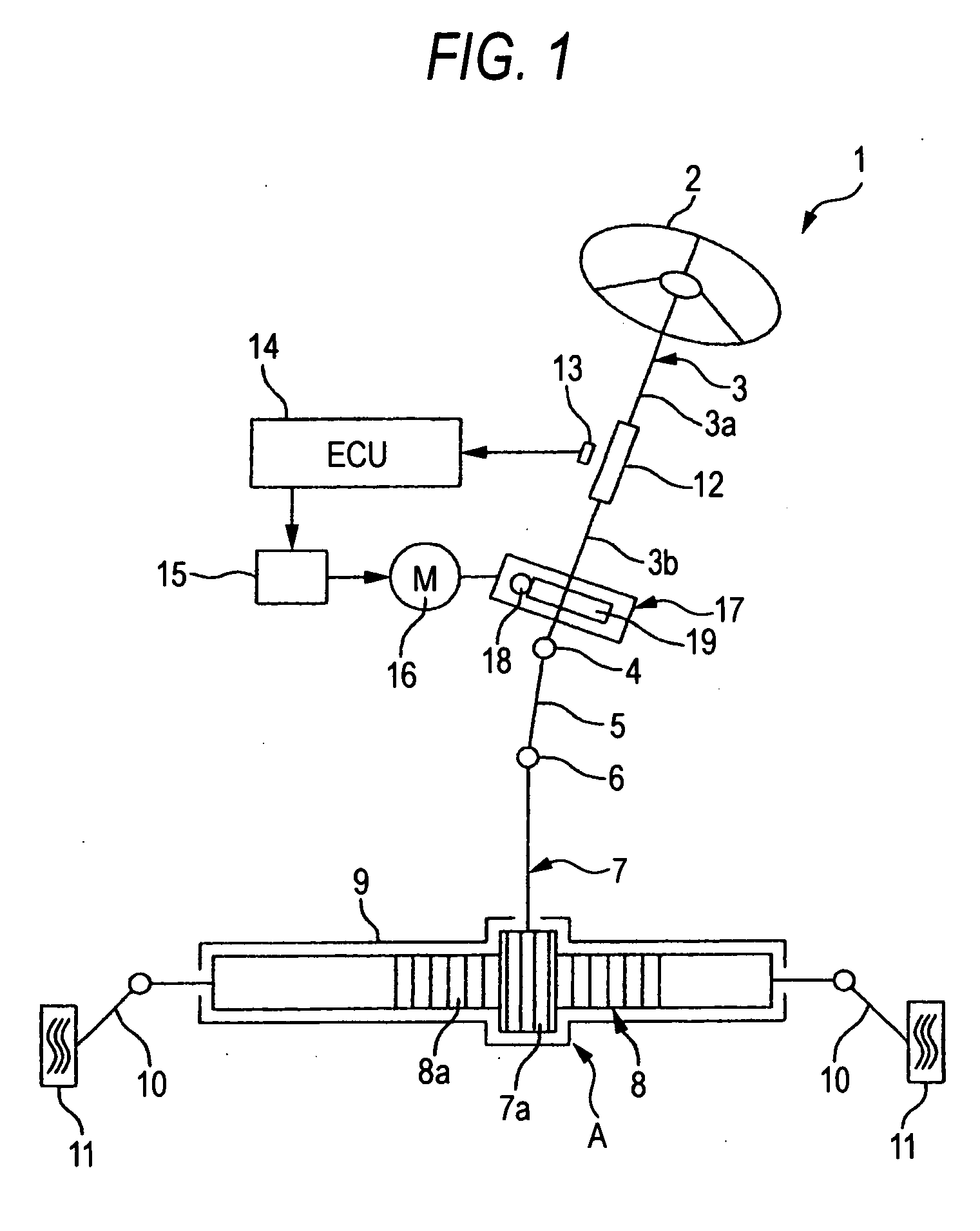
[0041] Embodiments of the invention will be described with reference to the accompanying drawings. FIG. 1 is a view schematically illustrating the constitution of an electric power steering system according to an embodiment of the invention.

[0042] Referring to FIG. 1, the electric power steering system 1 includes a steering shaft 3 coupled to a steering member 2 such as a steering wheel, an intermediate shaft 5 coupled to the steering shaft 3 via a universal joint 4, a pinion shaft 7 coupled to the intermediate shaft 5 via a universal joint 6, and a rack bar 8 having rack teeth 8a that mesh with pinion teeth 7a provided near an end of the pinion shaft 7 and serving as a steering shaft extending in the right-and-left direction of an automobile. The pinion shaft 7 and the rack bar 8 constitute a steering mechanism A of a rack-and-pinion mechanism.

[0043] The rack bar 8 is ...


PUM


Abstract

A curved leaf spring which is a first urging member surrounds an outer wheel of a second bearing, and urges, through the second bearing, a second end of a worm shaft in a direction in which the distance between the center of the worm shaft and the center of a worm wheel is shortened. A second urging member includes an annular support member received by an end surface of the outer wheel and a plurality of elastic pins extending in a direction in parallel with the axial direction of a support member. The elastic pins have fixed ends fixed to the support member and free ends that come into elastic contact with an end wall of a housing.

Description

BACKGROUND OF THE INVENTION [0001] This invention is related to an electric power steering system which produces a steering assisting force by an electric motor. [0002] An electric power steering system (EPS) for automobiles employs a reduction mechanism. In a column type EPS, for example, the revolution of the output shaft of the electric motor is reduced through a worm shaft and a worm wheel, whereby the output of the electric motor is amplified and is transmitted to a steering mechanism to assist the torque in the steering operation. [0003] A suitable degree of backlash is necessary for the meshing between the worm shaft and the worm wheel. When, for example, traveling on a rough road, however, there may generate teeth-hitting sound (rattling sound) due to the backlash reversely input from the road surface. [0004] To suppress the generation of teeth-hitting sound, it becomes necessary to strictly adjust the amount of backlash that occurs between the worm shaft and the worm wheel ...

Claims


Application Information

Patent Timeline
IPC IPC(8): B62D5/04F16C27/06F16H1/16F16H57/021
CPCB62D5/0409F16C27/04F16H57/021F16H2057/0213F16H55/24F16C2326/24F16C2361/61F16D3/68F16C19/06F16C23/08
Inventor YUASA, SUSUMUTAKAGI, YOSHIAKIKITAMI, ETSURO
Owner JTEKT CORP
Learn More