Radio receiving apparatus for receiving communication signals of different bandwidths

ommunication signal technology, applied in the field of radio receiving apparatus, can solve the problems of large power consumption, difficulty in realizing a sharply attenuating channel filter for separating a desired channel, and difficulty in achieving a radio receiving apparatus with many parts

Inactive Publication Date: 2001-10-23
PANASONIC CORP
View PDF16 Cites 24 Cited by
  • Summary
  • Abstract
  • Description
  • Claims
  • Application Information

AI Technical Summary

Benefits of technology

is to provide a superior radio receiving apparatus for receiving multi-band signals which apparatus is small in size and consumes a smaller amount of power.
As is apparent from FIG. 37(a), in principle, no active elements exist in the charge-transfer direction. Since processing is effected by charge transfer, it is unnecessary to supply new charge for identical information. Accordingly, the power consumption is basically low in the CCD. Further, all the operation is controlled by clock signals applied to the gate electrodes. However, since it is unnecessary to have the clock signals pass through switching elements, so that switching noise and the like is small.

Problems solved by technology

One of the causes for the fact that the high-frequency parts of the radio receiving apparatus are made complex is that it is very difficult to realize a sharply-attenuating channel filter for separating a desired channel band from its adjacent channels, and a desired filtering characteristic needs to be established step by step.
Therefore, the radio receiving apparatus requires numerous parts.
A second problem is that these numerous parts result in large power consumption.
Hence, since the operating speed of the operating portion becomes high and the operating amplitude in the digital system 42 is fixed and large at several volts, there is a drawback in that this results in an increase in power consumption which is several times greater than in a case where processing is effected by an analog system.
That is, even if the calculation clock rate is close to a baseband frequency, the total power consumption of the circuitry becomes (square of the voltage amplitude).times.(processing speed).times.(electrostatic capacitance of the circuit system load).times.(number of parallels), so that the total power consumption becomes large.
Namely, the fact that the signal is processed by a digital circuit has a negative factor for increasing the power consumption.
As a third problem, in a case where an attempt is made to digitize the signal processing, there results an increase in power consumption which is several times greater than in a case where processing is effected by a radio system.
As a fourth problem, conventional digital filters involve complicated calculations, and require the four rules of arithmetic even when their configurations are simple, so that power consumption is not negligible.
It may be said that this is possible in frequencies of AM radio bands, i.e., medium-wave broadcasting bands, which are handled by the conventional example of FIG. 39; however, in higher frequency bands such as those for TV broadcasting and cellular phone systems, no mixers are available which are capable of obtaining such large outputs.
Therefore, as a fifth problem, if a method using the A / D converters is adopted, there is a negative factor for substantially increasing the power consumption in the radio system or the analog system.
For this reason, as a sixth problem, trouble occurs in many communication schemes.
The first problem is that the radio receiving apparatus requires numerous parts for assuring favorable reception channel selectivity.
The second problem is that the numerous parts which present the aforementioned first problem incur large power consumption.
The third problem is that digitization of signal processing requires power consumption which is several times greater than analog processing.
The fourth problem is that the conventional digital filters involve complex calculations, so that their power consumption is large.
The fifth problem is that the A / D converters for signal digitization require large input signal amplitudes.
The sixth problem is that, in the direct-conversion receiving scheme whose local oscillation signal is equivalent to the carrier frequency of the received signal, the local oscillation signal interferes adjacent stations from the antenna, and a DC offset occurs, imparting errors to the demodulated signal.
In a communication system that utilizes many kinds of bandwidths, if filters are so prepared as to correspond to the respective bandwidths as in the above conventional examples, serious problems will occur in application to portable equipment and the like, such as an increase in size, increased complexity in shape, need for adding switches to peripheral sections, and an increase in power consumption due to parasitic capacitances.

Method used


Image

  • Radio receiving apparatus for receiving communication signals of different bandwidths
  • Radio receiving apparatus for receiving communication signals of different bandwidths
  • Radio receiving apparatus for receiving communication signals of different bandwidths

Examples


first embodiment

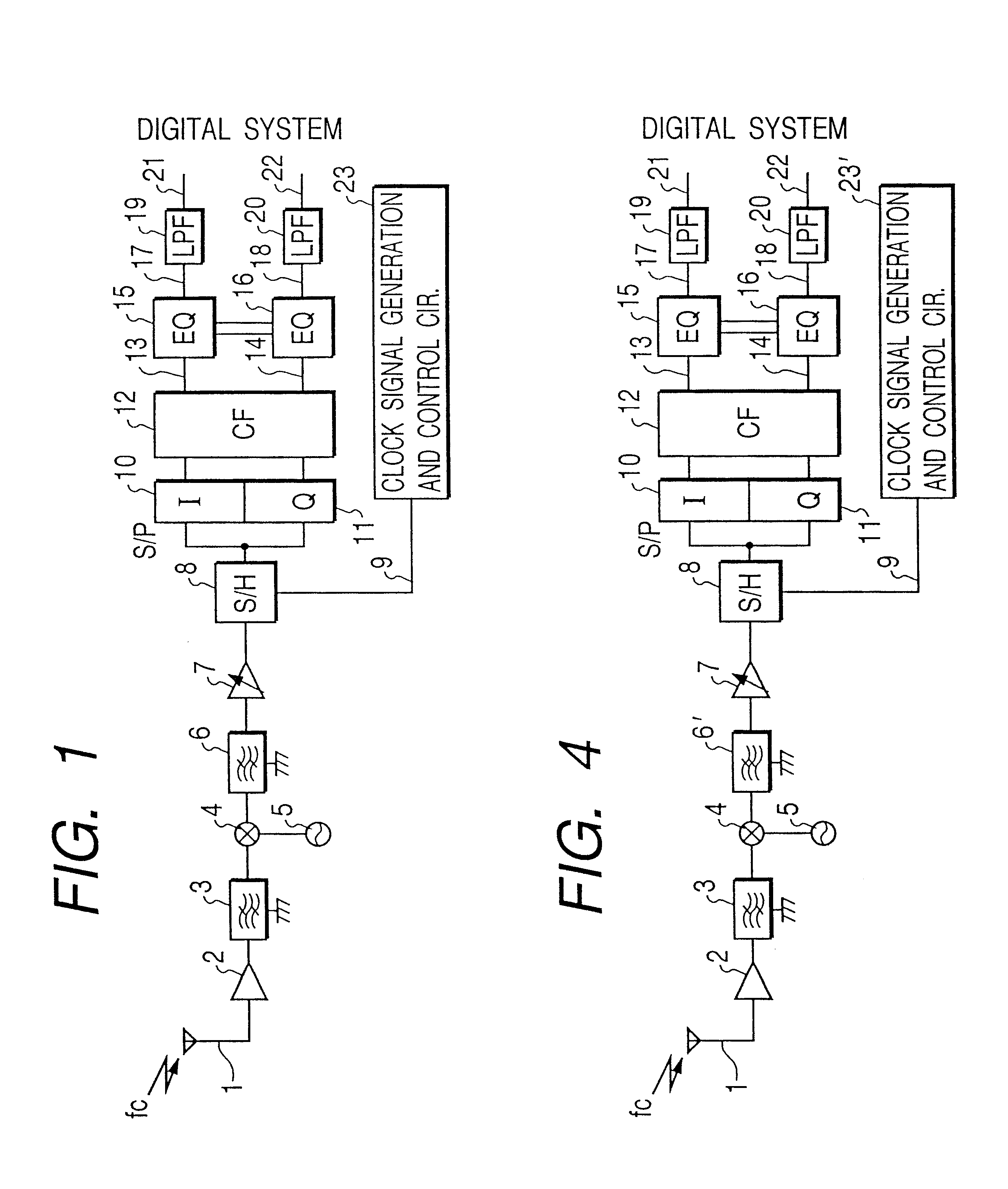
FIG. 1 shows a configuration of the present invention. A received signal 1 obtained from an antenna is supplied to and amplified by a high-frequency amplifier 2. An output from the high-frequency amplifier 2 is supplied to a first bandpass filter 3 to separate only signals of all the channels of a relevant communications system from other radio signals. An output from the first bandpass filter 3 is supplied to a frequency converter 4 where it is subjected to frequency conversion by use of a local oscillation frequency f.sub.LO.

An output from the frequency converter 4 is supplied to a second bandpass filter 6 so as to obtain a channel filtering effect whereby image signals which occur in the frequency converter 4 are absorbed and only desired waves are allowed to pass therethrough. An output from the second bandpass filter 6 is supplied to an AGC amplifier 7 from which an amplified signal is outputted with a predetermined signal strength. This output is supplied to a sample-and-hold ...

embodiment 2

FIG. 4 shows a configuration of a second embodiment of the invention. A received signal 1 obtained from an antenna is supplied to and amplified by a high-frequency amplifier 2. An output from the high-frequency amplifier 2 is supplied to a bandpass filter 3 to extract only signals of all the channels of the relevant communications system and filter out other radio signals. An output from the bandpass filter 3 is supplied to a frequency converter 4 where it is subjected to frequency conversion by use of a local oscillation frequency f.sub.LO, i.e., a frequency at a boundary between a desired wave and a lower channel adjacent thereto.

An output from the frequency converter 4 is supplied to a first-stage lowpass filter 6' so as to obtain a channel filtering effect whereby image signals which occur in the frequency converter 4 are absorbed and only desired waves are allowed to pass therethrough. An output from the first-stage lowpass filter 6' is supplied to an AGC amplifier 7 from which...

embodiment 3

FIG. 7 shows a configuration of a third embodiment of the invention. In FIG. 7, an I-axis decimation circuit 24, a Q-axis decimation circuit 25, and an image-rejecting frequency conversion circuit 26 are interposed between the I-axis lowpass filter 19 and a digital system 21' or between the Q-axis lowpass filter 20 and a digital system 22' in the FIG. 4 configuration of the second embodiment of the invention. In this connection, the control system of the clock-signal-generation and control circuit 23' is augmented.

A received signal 1 obtained from an antenna is supplied to and amplified by a high-frequency amplifier 2. An output from the high-frequency amplifier 2 is supplied to a bandpass filter 3 to extract only signals of all the channels of the relevant communications system and filter out other radio signals. An output from the bandpass filter 3 is supplied to a frequency converter 4 where it is subjected to frequency conversion by use of a local oscillation frequency f.sub.LO,...


PUM


Abstract

A received signal obtained from an antenna is subjected to high-frequency amplification. The amplified signal is supplied to a first bandpass filter, which extracts only signals of all the channels of a communications system concerned while filtering out other radio signals. The extracted signals are frequency-converted by using a local oscillation frequency, and only a desired wave is passed by a second bandpass filter. The desired wave is supplied to a sample-and-hold circuit, which performs sampling according to the bandwidth-limiting sampling theorem. A resulting discrete signal is supplied to an I-axis-component and Q-axis-component separating circuits, where the polarity of sample values is inverted for every other clock pulse with respect to each of the I and Q axes to thereby effect Hilbert transform. Resulting two orthogonal components on a phase plane are supplied to a complex coefficient filter.

Description

1. Field of the InventionThe present invention relates to a radio receiving apparatus used in mobile communications equipment, and more particularly to a radio receiving apparatus which can reduce the number of high-frequency circuit parts, and hence can reduce factors of high power consumption and factors causing unstable operation which factors are present in high-frequency circuits.The invention also relates to communications equipment which transmits information while changing the bandwidth in accordance with its type, and more particularly it is intended to implement, in a simple configuration, a radio receiving apparatus for receiving communication signals of different bandwidths.2. Description of the Related ArtOne of the important points of a radio receiving apparatus in mobile communications equipment is how to reduce the number of high-frequency circuit parts to reduce factors of high power consumption and factors causing unstable operation, which are present in high-frequ...

Claims


Application Information

Patent Timeline
Patent Type & Authority Patents(United States)
IPC IPC(8): H03D3/00H04B1/26H04B1/30H04B1/16
CPCH03D3/009H04B1/0014H04B1/0039H04B1/26H04B1/30H03D3/006H03D3/007H04B1/16
Inventor OHTA, GEN-ICHIROINOGAI, KAZUNORISUDO, HIROAKISASAKI, FUJIO
Owner PANASONIC CORP
Why Eureka
Try Eureka