Optical system, and optical apparatus

a technology of optical system and optical apparatus, applied in the direction of printers, instruments, camera focusing arrangement, etc., can solve the problems of increased power consumption, inability to vary the focal length of the lens, complicated mechanical structure, etc., and achieve the effects of reducing power consumption, reducing noise, and reducing nois

Inactive Publication Date: 2005-09-27
OLYMPUS CORP
View PDF7 Cites 28 Cited by
  • Summary
  • Abstract
  • Description
  • Claims
  • Application Information

AI Technical Summary

Benefits of technology

[0006]In view of such problems as discussed above, a primary object of the invention is to provide an optical system represented by a lens system comprising a variable-shape mirror having a reflecting surface capable of focusing or a lens system comprising a variable-focus lens, which has limited power consumptions, produces little or no noise and ensures fast response, simple mechanical structure and cost reductions, and optical apparatus comprising such an optical system.
[0016](9) An image pickup system comprising an optical element having variable optical properties and an image pickup device, characterized in that to compensate for a change in the tilt of an image-formation surface in association with a change in the optical element having variable optical properties, the image pickup device is decentered or tilted, thereby compensating for a decrease in image-formation performance in association with the change in the optical element having variable optical properties.

Problems solved by technology

Referring to conventional lenses formed of polished glass materials, their focal length cannot be varied because they cannot transform by themselves.
For this reason, mechanical structures become complicated, which are used to move said lenses or lens groups comprising the same in an axial direction for focusing and zooming.
Since motors, etc. are used to mechanically move some of the lens groups, there are problems such as increased power consumptions, noisy sounds, slow response speeds, and time-consuming movement of lens groups.
Even for phototaking or observations while camera shake is prevented, lens groups are mechanically moved with motors, solenoids, etc., resulting in problems such as increased power consumptions, cost rises due to complicated mechanical structures.

Method used


Image

  • Optical system, and optical apparatus
  • Optical system, and optical apparatus
  • Optical system, and optical apparatus

Examples


embodiment 1

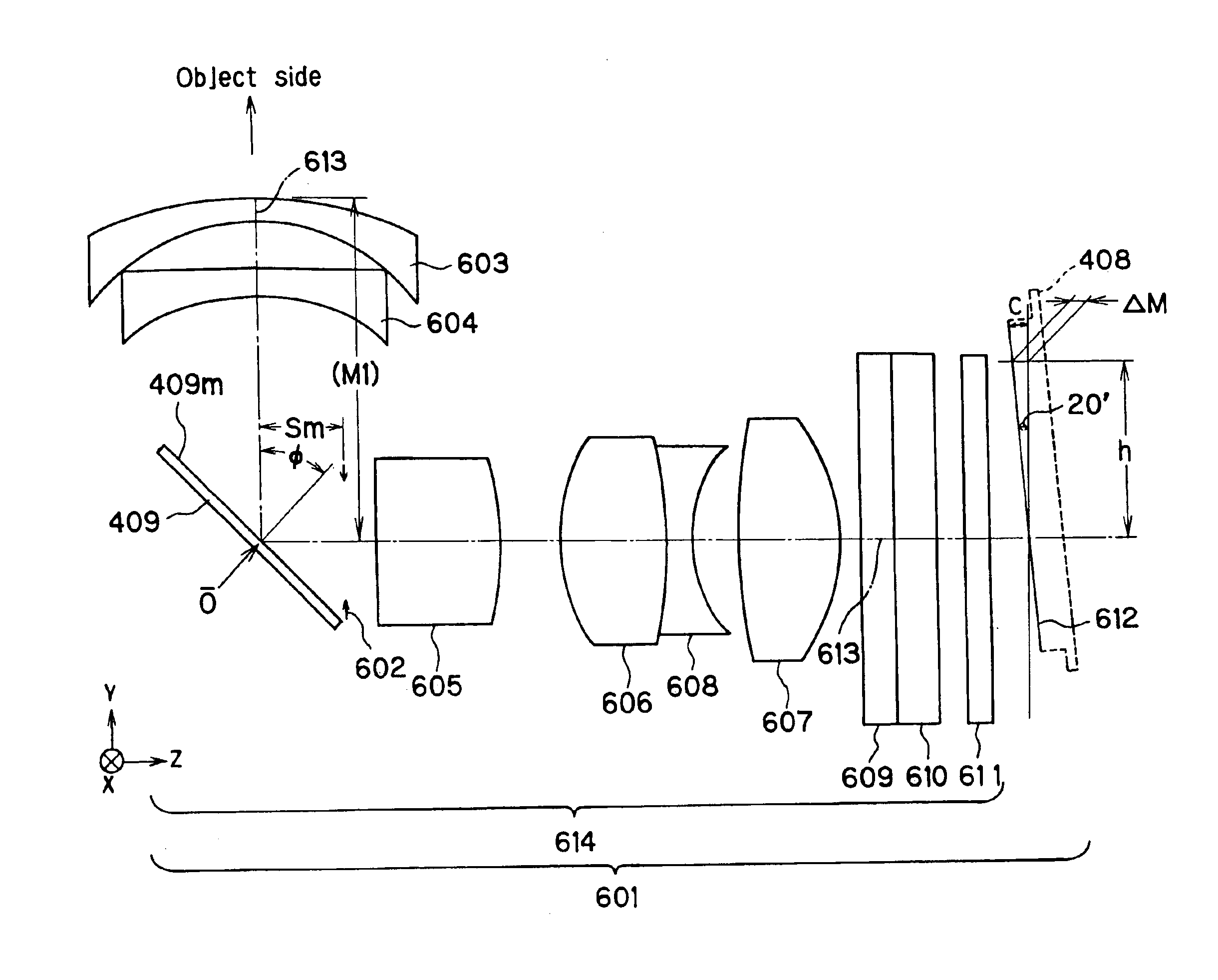
[0408]This embodiment is directed to an image pickup optical system 614 in which the optical system of FIG. 39 is used, as shown in the Y-Z sectional view of FIG. 45. As shown in FIG. 45, the respective optical elements are located in order from the object side of the optical system. The first two elements are negative meniscus lenses 603 and 604, each convex on its object side, in the rear of which there is located a variable mirror 409. In the rear of the variable mirror 409, there are located a stop 602, then a double-convex positive lens 605 having an aspheric surface on its image side, then a doublet consisting of a double-convex positive lens 606 and a double-concave negative lens 608, and finally a double-convex positive lens 607 having an aspheric surface on its image side. In the rear of the positive lens 607, there are located a low-pass filter 609, then an infrared cut filter 610, and finally a cover glass 611, in the rear of which there is located an image pickup surface...

embodiment 2

[0411]This embodiment is the same in lens arrangement as Embodiment 1. As shown in the Y-Z sectional view of FIG. 46, the respective optical elements are located in order from the object side of the optical system. The first two elements are negative meniscus lenses 603 and 604, each convex on its object side, in the rear of which there is located a variable mirror 409. In the rear of the variable mirror 409, there are located a stop 602, then a double-convex positive lens 605, then a doublet consisting of a double-convex positive lens 606 and a double-concave negative lens 608, and finally a double-convex positive lens 607. In the rear of the positive lens 607, there are located a low-pass filter 609, then an infrared cut filter 610, and finally a cover glass 611, in the rear of which there is located an image pickup surface 612 of a solid-state image pickup device, which is tilted at an angle C of tilt with respect to a plane vertical to an optical axis 613 at an object distance ∞...

embodiment 3

[0414]The image pickup optical system of this embodiment is much the same in lens arrangement as that of Embodiment 1. As shown in the Y-Z sectional view of FIG. 47, in order from the object side of the image pickup optical system there are located a negative meniscus lenses 603 and 604, each convex on its object side. In the rear of the lens 604, there is located a variable mirror 409 that also serves as an aperture stop. In the rear of the variable mirror 409, there are located a positive meniscus lens 605 convex on its image plane side, then a doublet consisting of a double-convex positive lens 606 and a double-concave negative lens 608 and finally a double-convex positive lens 607. In the rear of the lens 607, there are located a low-pass filter 609, then an infrared cut filter 610 and finally a cover glass 611. In the rear of the cover glass 611, there is located an image pickup surface 612 of a solid-state image pickup device. In the image pickup optical system, lens systems c...


PUM


Abstract

The invention relates to an optical system or apparatus such as a lens system capable of focus control and a variable-focus lens, which has reduced power consumptions, ensures noiseless operation and fast response and contributes to cost reductions for the reason of simplified structure. Specifically, the invention provides an optical apparatus comprising an element 409 having variable optical properties and an image plane 612. To correct the optical apparatus for movement of the image-formation surface of an optical system 614 in association with a change in the element 409 having variable optical properties, the image plane 612 is placed in the range of movement of the image-formation surface in association with the change in the element having variable optical properties.

Description

[0001]This is a divisional application of U.S patent application Ser. No. 10 / 358,362, filed on Feb. 5, 2003 now U.S. Pat. No. 6,833,966, which claims the benefit of Japanese Application Nos. 2002-28569, filed on Feb. 5, 2002 and 2002-45938, filed on Feb. 22, 2002. the contents of all of which are hereby incorporated by reference in their entireties.BACKGROUND OF THE INVENTION[0002]The present invention relates to an optical system and an optical apparatus, and more particularly to an optical system comprising a focus-controllable optical element having variable optical properties represented by a variable-shape mirror and optical apparatus comprising said optical system, e.g., video projectors, digital cameras, TV cameras, endoscopes and camera finders.[0003]Referring to conventional lenses formed of polished glass materials, their focal length cannot be varied because they cannot transform by themselves. For this reason, mechanical structures become complicated, which are used to m...

Claims


Application Information

Patent Timeline
Patent Type & Authority Patents(United States)
IPC IPC(8): G02B15/14G02B26/08G02B13/00G02B3/12G02B3/14G02B5/18G03B13/06G02B5/04G02B5/10G02B7/04G02B7/10G02B13/18G02B15/00G02B17/08G02B25/00G03B21/00H04N5/225
CPCG02B3/14G02B5/1828G02B13/004G02B13/0065G02B13/0075G02B13/009G02B17/0896G02B26/0825G03B3/10G03B2205/0046G03B2205/0053
Inventor NISHIOKA, KIMIHIKOYASUDA, EIJISEKIYAMA, KENTARONAGATA, TETSUO
Owner OLYMPUS CORP
Why Eureka
Try Eureka