BIM and display of 3D models on client devices

a client device and 3d model technology, applied in the field of bim and display of 3d models on client devices, can solve the problems of large computational power for rendering images, time-consuming, and insufficient storage space, and achieve the effect of less power consumption and less storage capacity

Inactive Publication Date: 2014-08-07
DALUX APS
View PDF10 Cites 37 Cited by
  • Summary
  • Abstract
  • Description
  • Claims
  • Application Information

AI Technical Summary

Benefits of technology

[0010]Further, there is a need to reduce the CPU time necessary for complex calculations in order to increase the working speed of computers and mobile devices. There also exists a need to limit the consumption of power on a computer or a mobile device. Related to this, there is a need to limit the heat produced by computers and mobile devices.
[0090]This embodiment allows the client device to calculate a new image, by simple manipulation of images without the need of a complex 3D calculation necessitating a large model. Naturally, these steps may be performed several times to show additional details hidden behind other objects.

Problems solved by technology

Large 3D models may use of the order of 1 gigabyte of memory, and require large computational power for rendering images, which may additionally be time consuming.
A client device, such as a tablet device, for example using a web browser, may not have sufficient storage space for the 3D model, and even with sufficient memory the rendering of images may be time consuming.
Further, the transfer of an entire 3D model by a network may be bandwidth and time consuming and thus costly.
For a viewer of the building it is inconvenient to have to change from one part model to another, when examining different parts of the building.

Method used


Image

  • BIM and display of 3D models on client devices
  • BIM and display of 3D models on client devices
  • BIM and display of 3D models on client devices

Examples


example 1

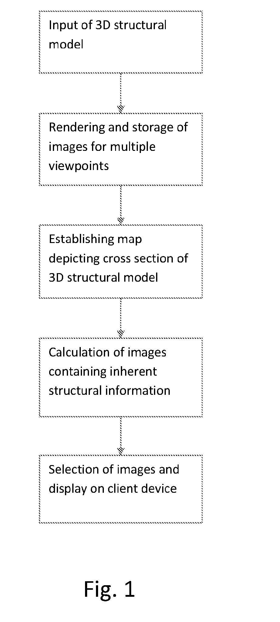
[0126]The following is an example which describes an embodiment of the present invention. Reference is made to FIG. 3.

(1) Establishing Model

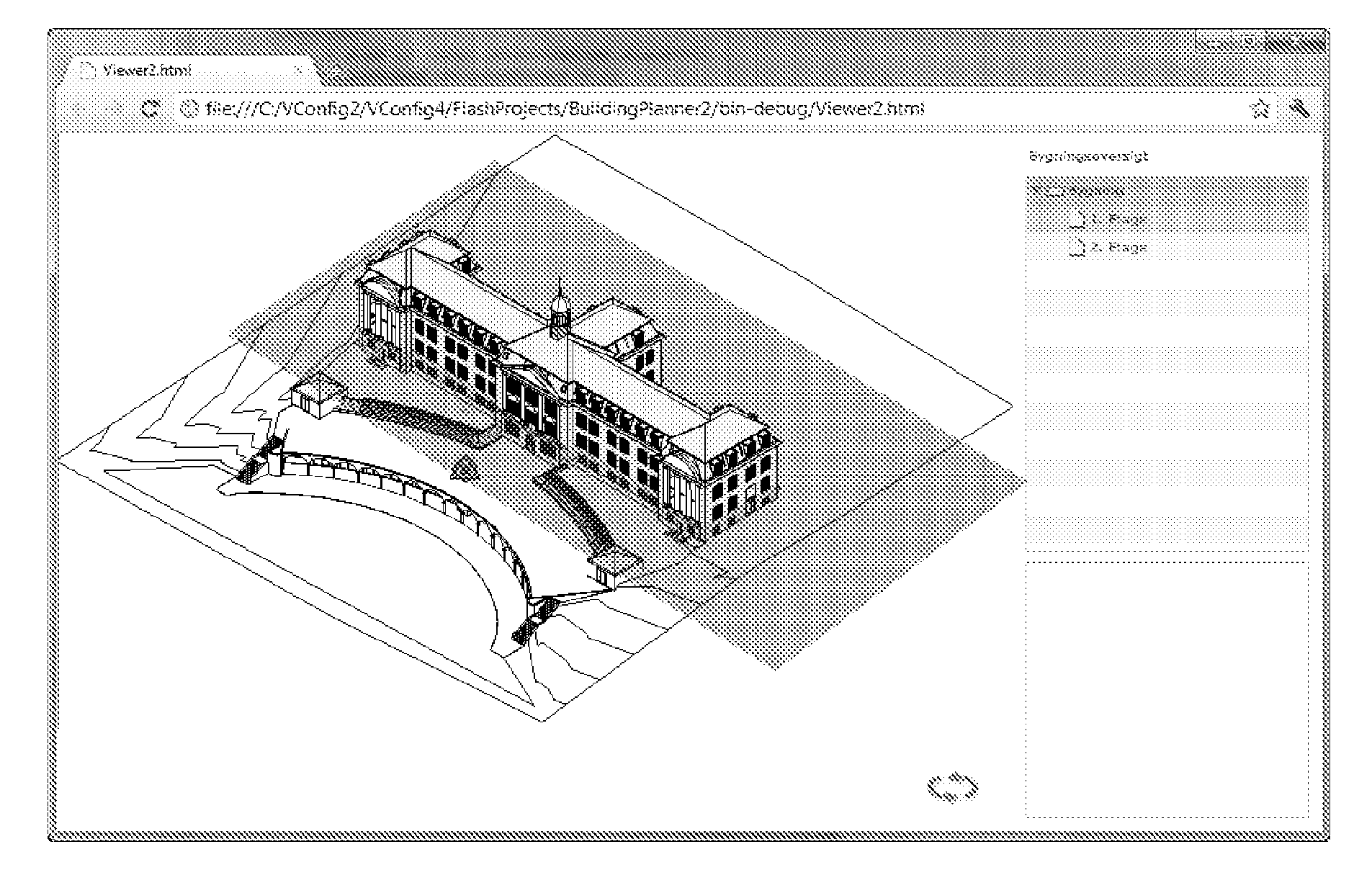
[0127]The model is a digital model of a building loaded from the IFC format. The digital model contains a 3D model, at several cross-sections and metadata on the objects.

(2) Calculations

[0128]The processor takes the building model as input and creates part (3), (4) and (5).

(3) Sets of Images

[0129]The sets of images are cubemaps generated on a number of positions. A large number of positions are generated close to the building, while a few positions are generated some distance from the building. A simple algorithm is generating a 3D grid with 1 meter spacing on a bounding box of the building. Further, multiple positions are generated with a fixed distance to cross-sections making it easy to select a 3D position from a cross section view. A cubemap is generated depicting the 3D surroundings at each position. The images are stored in the jpg format...

example 2

[0137]The following is an example which describes an embodiment of the present invention, wherein the client device replaces a visible object with objects hidden behind the visible object. Reference is made to FIG. 11a-c ID, which are six image representations of depicted images and metadata. For explanatory purposes two-dimensional images are used here, while complete cubemaps may be used in an actual implementation.

[0138]The six images of FIG. 11a-FIG. 11c ID have the same number of pixel, and the same dimensions, i.e. the same width and the same height. FIG. 11a shows an image with the objects denoted (1), (2) and (3). FIG. 11a ID is image formatted data comprising the corresponding metadata.

[0139]As an example, the image of FIG. 11a is displayed on a client device. When a user selects an object visible on FIG. 11a, e.g. object (2), the client device will use the metadata of FIG. 11a ID to identify which parts of the displayed image belongs to the object, i.e. the part denoted (2...


PUM


Abstract

The invention relates to the calculation of 2D images from a 3D model, wherein the 2D images may be generated on a computer device and stored on a server for subsequent display on a client device.

Description

[0001]The present invention relates to a system and a method for displaying images on a client, such as a client device, wherein the images have been calculated from a 3D model. In particular the invention relates to the calculation of images from a 3D model, wherein the images may be generated on a computer device and stored on a server for subsequent retrieval and display on a client device.TECHNICAL BACKGROUND[0002]The patent application EP 1890262 A1 proposes generating a virtual 3D model utilizing photographs of a 3D object from multiple different viewing positions as 2D views, and storing the generated virtual 3D model for display retrieval.[0003]The patent application US 2005 / 0028111 describes an orientation indicator graphical user interface element in a display view of a three-dimensional scene.[0004]The patent application US 2005 / 0243083 describes a computer-implemented system allowing a user to access metadata associated with an image being displayed to a user.[0005]The p...

Claims


Application Information

Patent Timeline
Patent Type & Authority Applications(United States)
IPC IPC(8): G06T17/05
CPCG06T2219/20G06T17/05G06T15/20G06T19/00G06T2210/04G06F30/00G06F2111/02
Inventor DALGAARD LARSEN, BENT
Owner DALUX APS
Why Eureka
Try Eureka