Ultrasonic Surgical System Having A Fluid Cooled Blade And Related Cooling Methods Therefor

a technology of ultrasonic dissector and blade, which is applied in the field of ultrasonic dissector with fluid cooling components, can solve problems such as tissue damage, and achieve the effect of effectively cooling waveguides, blades or other components

Active Publication Date: 2013-03-21
TYCO HEALTHCARE GRP LP
View PDF6 Cites 35 Cited by
  • Summary
  • Abstract
  • Description
  • Claims
  • Application Information

AI Technical Summary

Benefits of technology

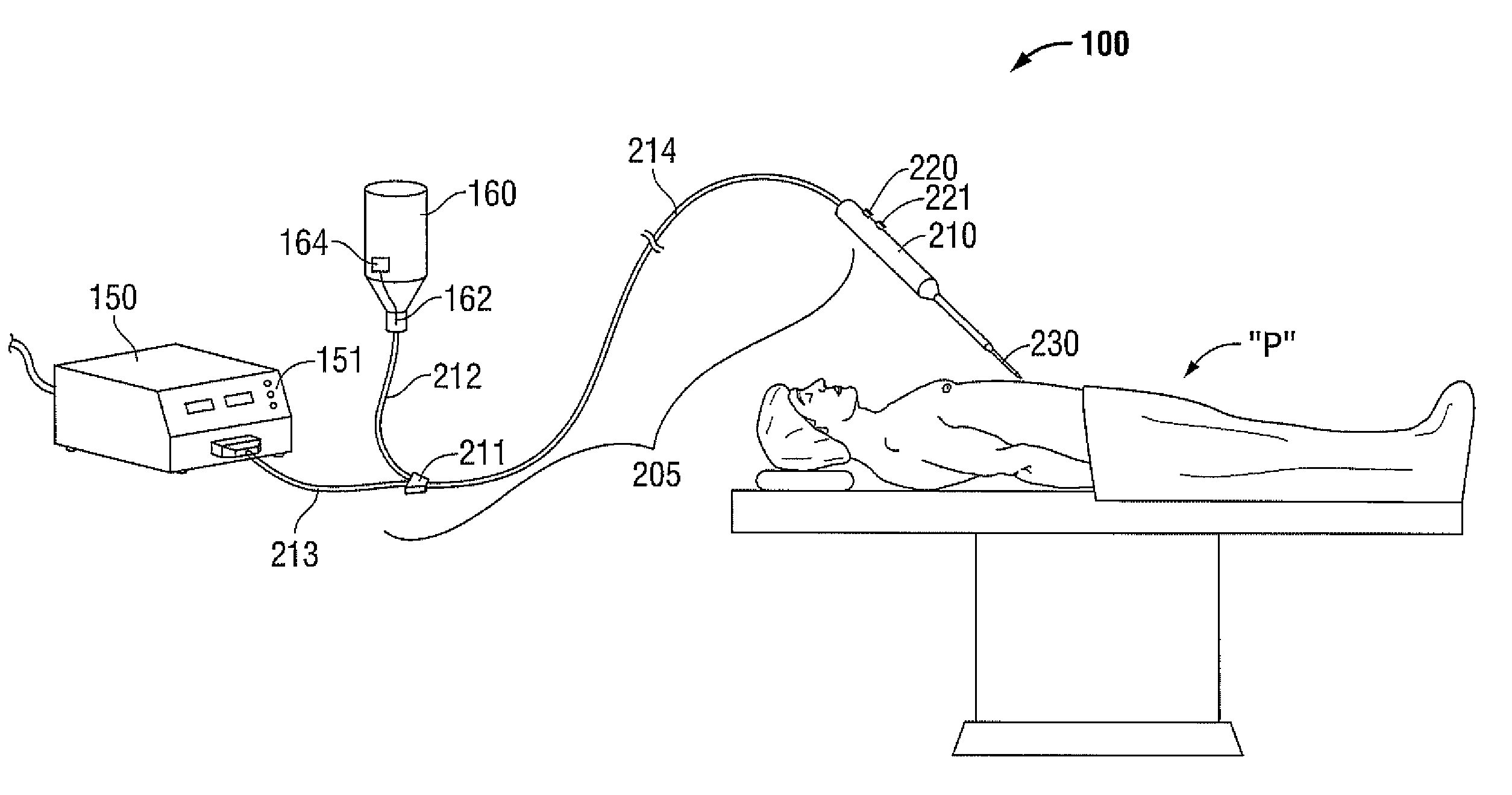
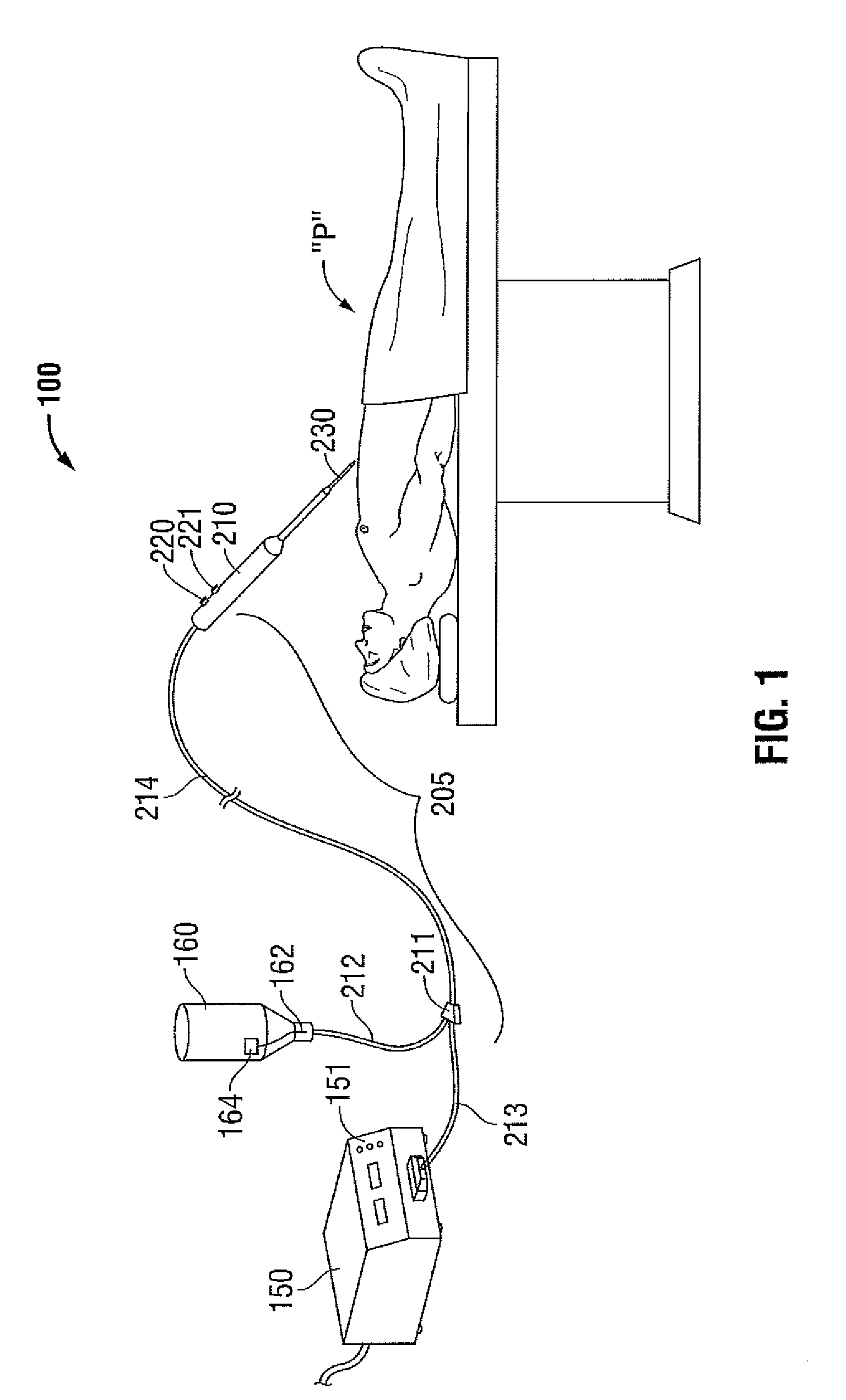
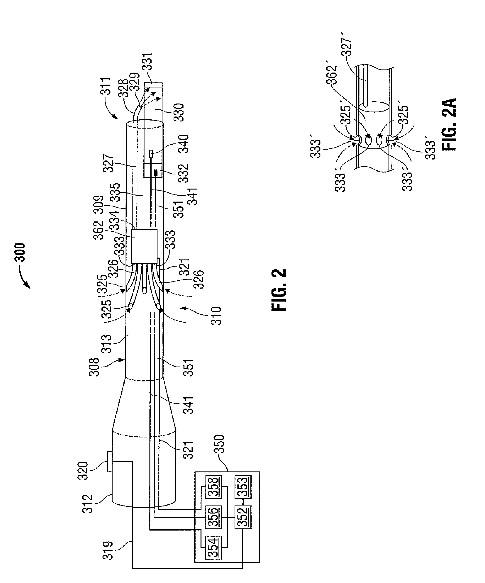
[0008]The present disclosure is directed to an ultrasonic instrument having a shaft, a waveguide blade at a distal end of the shaft, and one or more cooling ducts disposed at a distal end of the shaft and configured to direct a cooling fluid to the waveguide. The cooling fluid may include air, CO2, and / or saline, which are commonly available in a surgical environment and possess the thermal mass necessary to effectively cool a waveguide, blade, or other component of an ultrasonic instrument. Also disclosed is a coolant delivery unit adapted to deliver fluid to the instrument that may include, without limitation, a fan, an impeller, a pump, a syringe, or a bellows. The coolant delivery unit may be internal or external to the ultrasonic instrument. The coolant delivery unit may be activated automatically, or under control of a surgeon. The coolant delivery unit may also be operatively associated with a temperature sensor and / or activated at one or more predefined temperatures. The cooling fluid may also aid in cleaning the tip of the device and / or the surgical field. In some embodiments, the cooling fluid may be stored for use within a reservoir that is external to the instrument. In some embodiments, the instrument is configured to utilize fluid contained an insufflated cavity within a patient, such as, without limitation, a pneumoperitoneum.

Problems solved by technology

During use, waveguides on ultrasonic dissection devices can reach temperatures greater than 200° C. If an overheated waveguide is touched to tissue, the tissue can be damaged.

Method used


Image

  • Ultrasonic Surgical System Having A Fluid Cooled Blade And Related Cooling Methods Therefor
  • Ultrasonic Surgical System Having A Fluid Cooled Blade And Related Cooling Methods Therefor
  • Ultrasonic Surgical System Having A Fluid Cooled Blade And Related Cooling Methods Therefor

Examples


Embodiment Construction

[0025]Particular embodiments of the present disclosure are described hereinbelow with reference to the accompanying drawings; however, it is to be understood that the disclosed embodiments are merely examples of the disclosure, which may be embodied in various forms. The terminology used herein is for the purpose of describing particular embodiments only, and is not intended to be limiting. Well-known and / or repetitive functions and constructions are not described in detail to avoid obscuring the present disclosure in unnecessary or redundant detail. Therefore, specific structural and functional details disclosed herein are not to be interpreted as limiting, but merely as a basis for the claims and as a representative basis for teaching one skilled in the art to variously employ the present disclosure in virtually any appropriately detailed structure. In the drawings and in the descriptions that follow, In the drawings and in the descriptions that follow, the term “proximal,” as is ...


PUM


Abstract

The present disclosure is directed to a fluid cooled ultrasonic surgical instrument and related systems and methods of use therefor. In some embodiments, the disclosed ultrasonic surgical instrument is adapted for used within an insufflated cavity or pneumoperitoneum of a patient. The instrument includes a housing having an elongate shaft, a waveguide disposed at a distal end of the shaft, a coolant inlet port defined in an outer surface of the housing, and a coolant pump disposed within the housing and configured to move coolant from the coolant inlet port to the waveguide. During use, insufflation gas from within the pneumoperitoneum is drawn into the instrument shaft by the coolant pump, and blown over the waveguide to provide cooling. The delivery of ultrasonic energy and activation of the pump may be controlled by a processor in response to user input and waveguide temperature.

Description

BACKGROUND[0001]1. Technical Field[0002]The present disclosure relates generally to surgical instruments, and in particular, to an ultrasonic dissector having fluid-cooled components and related methods of cooling components of an ultrasonic surgical instrument.[0003]2. Background of Related Art[0004]Energy-based tissue treatment is well known in the art. Various types of energy (e.g., electrical, ultrasonic, microwave, cryogenic, thermal, laser, etc.) are applied to tissue to achieve a desired result. Ultrasonic energy may be delivered to tissue using a surgical probe that includes a transducer coupled with an end effector, and configured to deliver ultrasonic energy to tissue.[0005]The use of ultrasonic energy in surgical procedures is known to those skilled in the art to be a valuable resource for cutting and fragmenting tissue of a patient. Most of these apparatus incorporate a sinusoidal driving signal which causes the mechanical tip of a waveguide to vibrate at a selected freq...

Claims


Application Information

Patent Timeline
Patent Type & Authority Applications(United States)
IPC IPC(8): A61B17/32
CPCA61B17/3474A61B2017/22021A61B2017/00106A61B17/320068A61B17/3211A61B2017/320084
Inventor ROSS, ANTHONY B.STODDARD, ROBERT B.CUNNINGHAM, JAMES S.DICKHANS, WILLIAM J.HEMPSTEAD, RUSSELL D.LARSON, ERIC R.KERR, DUANE E.NAU, JR., WILLIAM H.WARD, ARLEN K.
Owner TYCO HEALTHCARE GRP LP
Why Eureka
Try Eureka