Highly efficient projection system

a projection system and high-efficiency technology, applied in the field of projection systems, can solve the problems of complex and expensive systems, single-panel systems providing only 13 of the optical efficiency of three-panel projection systems, and achieve the effects of increasing light efficiency, high efficiency and compactness

Inactive Publication Date: 2006-08-29
SAMSUNG ELECTRONICS CO LTD
View PDF17 Cites 36 Cited by
  • Summary
  • Abstract
  • Description
  • Claims
  • Application Information

AI Technical Summary

Benefits of technology

[0017]An apparatus consistent with the present invention relates to a highly efficient and compact projection system utilizing a single scrolling unit to scroll color bars, which can increase the light efficiency by effectively utilizing polarization components.

Problems solved by technology

The 3-panel projection systems provide better optical efficiency than the single-panel projection systems, but are generally more complicated and expensive.
However, these single-panel systems provide only ⅓ of the optical efficiency of the three-panel projection systems because red (R), green (G), and blue (B) colors into which white light is separated are used sequentially.
Hence, the optical system becomes bulky, and the manufacture and assembly thereof is complicated, thus degrading the yield.
Three motors for rotating three scrolling prisms for three color beams generate a lot of noise during operation.
Additionally, a projection system utilizing three motors is manufactured at a greater cost than a color wheel type projection system which utilizes a single motor.
However, controlling the synchronization is not easy.
Due to the circular motion of the scrolling prisms 114, 135, and 142, the color scrolling speed by the three scrolling prisms is irregular, consequently deteriorating the quality of the resultant image.
However, the PCS 105 having the above-described structure generates a beam loss because of cell boundaries of the second lens array 104.
Further, this structure is complicated.

Method used


Image

  • Highly efficient projection system
  • Highly efficient projection system
  • Highly efficient projection system

Examples


Embodiment Construction

[0050]The present invention will now be described more fully with reference to the accompanying drawings, in which exemplary embodiments of the invention are shown. In the drawings, like reference numbers refer to like elements throughout, and the sizes of elements may be exaggerated for clarity.

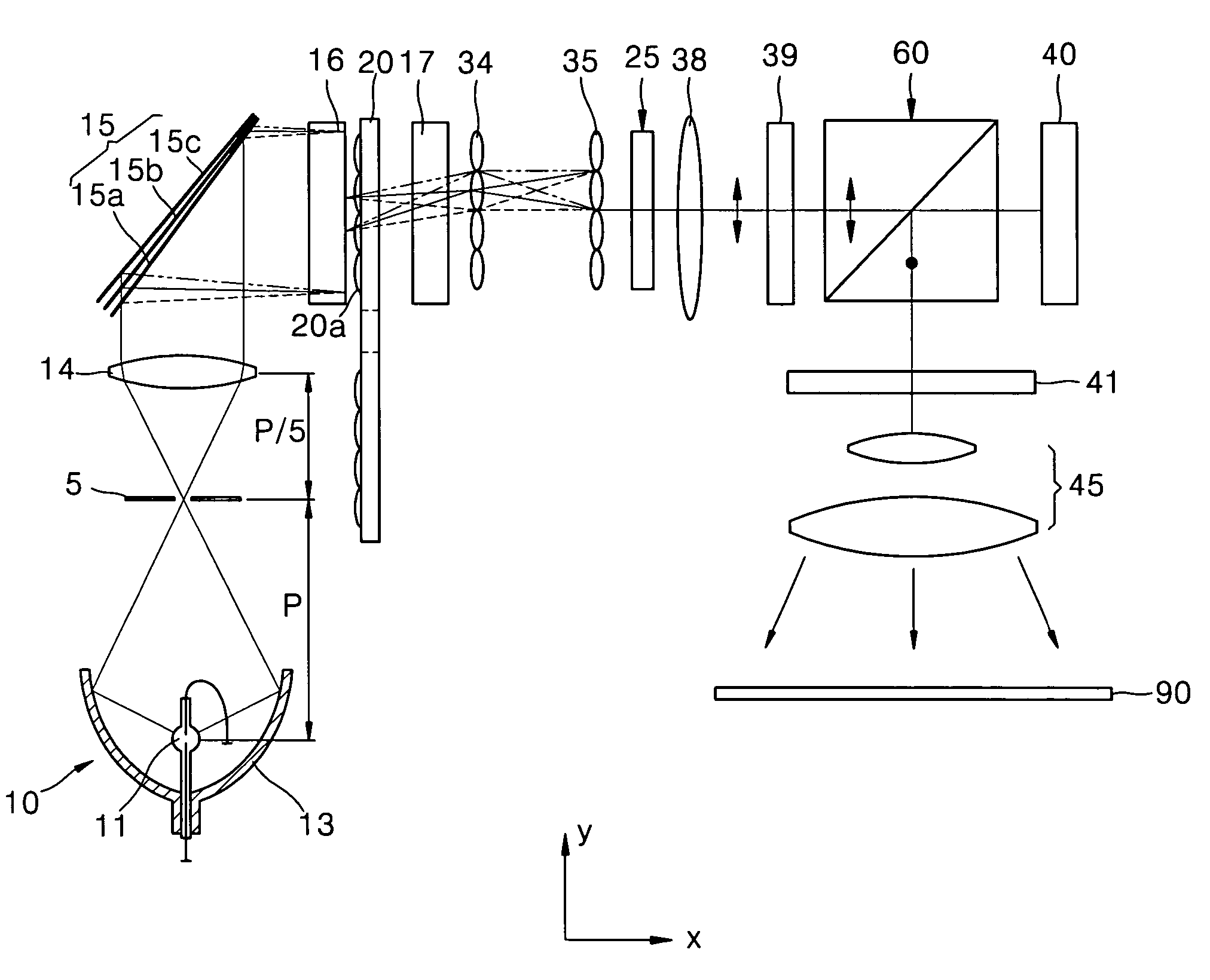
[0051]FIG. 4 is a schematic diagram of a projection system according to a first exemplary embodiment of the present invention. Referring to FIG. 4, the projection system according to the first exemplary embodiment of the present invention includes a light source 10, a color separator 15, a scrolling unit 20, a polarization conversion system (PCS) 25, a light valve 40, and a projection lens unit 45. The color separator 15 separates light emitted from the light source 10 according to color. The scrolling unit 20 scrolls R, G, and B color beams, into which light has been separated by the color separator 15. The PCS 25 converts the beams scrolled by the scrolling unit 20 into beams having a sing...


PUM


Abstract

A highly efficient projection system is provided, including a light source, a color separator, a scrolling unit, a light valve, a projection lens unit, and a polarization conversion system. The color separator separates an incident beam according to color. The scrolling unit includes at least one lens cell and converts a rotation of the lens cell into a rectilinear motion of an area of the lens cell through which light passes so the incident beam is scrolled. The light valve processes a beam transmitted by the color separator and the scrolling unit, according to an image signal and forms a color picture. The projection lens unit magnifies the color picture formed by the light valve and projects the magnified color picture onto a screen. The polarization conversion system is installed between the color separator and the light valve and converts the incident beam into a beam with a single polarization.

Description

[0001]This application claims the priority of Korean Patent Application No. 2003-33243, filed on May 24, 2003, in the Korean Intellectual Property Office, and the benefit of U.S. Patent Provisional Application No. 60 / 457,918, filed on Mar. 28, 2003, in the U.S. Patent and Trademark Office, the disclosures of which are incorporated herein in their entirety by reference.BACKGROUND OF THE INVENTION[0002]1. Field of the Invention[0003]The present invention relates to a projection system, and more particularly, to a highly efficient projection system which can be made more compact by using a single scrolling unit to scroll color bars and more light efficient by effectively utilizing polarization components.[0004]2. Description of the Related Art[0005]In general projection systems, a light valve, such as a liquid crystal display (LCD) or a Digital Micro-mirror Device (DMD), controls the on / off operation of light emitted from a light source on a pixel-by-pixel basis and forms a picture. A ...

Claims


Application Information

Patent Timeline
Patent Type & Authority Patents(United States)
IPC IPC(8): G03B21/14G02B27/14H04N9/31
CPCG02B27/1033G02B27/145H04N9/3197H04N9/3117G02B27/148G03B21/14
Inventor KIM, DAE-SIKCHO, KUN-HOKIM, SUNG-HALEE, HEE-JOONG
Owner SAMSUNG ELECTRONICS CO LTD
Why Eureka
Try Eureka