Lighting apparatus using light emitting diode
a light-emitting diode and light-emitting technology, which is applied in outdoor lighting, lighting heating/cooling arrangements, and protection devices for lighting, etc., can solve the problems of short life span and high power consumption, difficulty in arbitrarily adjusting the brightness of diffusion range, and limitations in forming sufficient light distribution to effectively illuminate objects, etc., to improve lighting efficiency and improve flexibility in lighting design.
- Summary
- Abstract
- Description
- Claims
- Application Information
AI Technical Summary
Benefits of technology
Problems solved by technology
Method used
Image
Examples
first embodiment
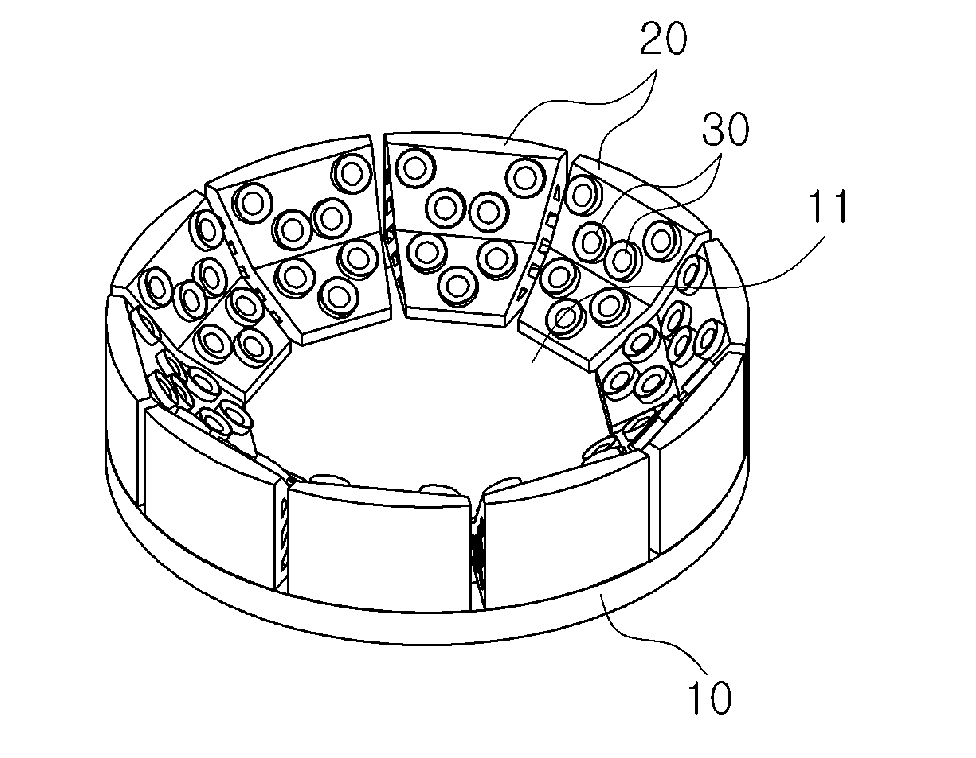
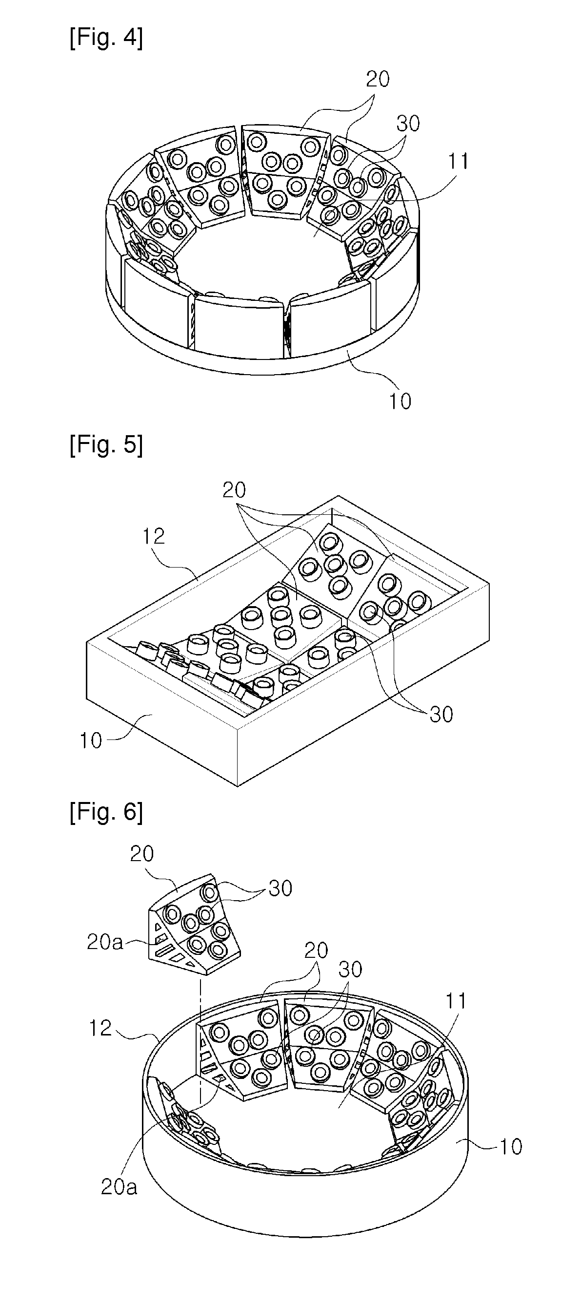
[0080]The first embodiment forms a narrow light distribution type using the base body member 10 having a rectangular box shape with its upper surface being opened, which includes the rectangular mounting surface 11 and the side portion 12 that protrudes vertically from the edge of the mounting surface 11 with a predetermined height, as shown in FIG. 17.
[0081]In this embodiment, the lengthwise direction of the rectangular mounting surface 11 is the horizontal direction and the widthwise direction thereof is the vertical direction.
[0082]The inclined block members 20 in the first embodiment, as shown in FIG. 18, are arranged in two rows in the lengthwise direction of the mounting surface 11, and the first row includes two 5° blocks 21 mounted at the center of the mounting surface 11 so as to face each other in the lengthwise direction thereof and a pair of 40° blocks 25 mounted at the outsides of the 5° blocks 21 so as to face each other in the widthwise direction.
[0083]The second row ...
second embodiment
[0086]The second embodiment forms an intermediate light distribution type using the base body member 10 having a rectangular box shape with its upper surface being opened, which includes the rectangular mounting surface 11 and the side portion 12 that protrudes vertically from the edge of the mounting surface 11 with a predetermined height, as shown in FIG. 20.
[0087]In this embodiment, the lengthwise direction of the rectangular mounting surface 11 is the horizontal direction and the widthwise direction thereof is the vertical direction.
[0088]The inclined block members 20 in the second embodiment, as shown in FIG. 20, include two pairs of 5° blocks 21 mounted at the center of the mounting surface 11 so as to face each other in the widthwise direction thereof and a pair of 30° blocks 24 mounted at the outsides of the 5° blocks 21 so as to face each other in the lengthwise direction of the mounting surface 11.
[0089]Five second light emitting diode modules 32 each provided with a 30° l...
third embodiment
[0091]The third embodiment forms an intermediate light distribution type using the base body member 10 having a rectangular box shape with its upper surface being opened, which includes the rectangular mounting surface 11 and the side portion 12 that protrudes vertically from the edge of the mounting surface 11 with a predetermined height, as shown in FIG. 23.
[0092]In this embodiment, the lengthwise direction of the rectangular mounting surface 11 is the horizontal direction and the widthwise direction thereof is the vertical direction.
[0093]The inclined block members 20 in the third embodiment, as shown in FIG. 24, include two pairs of 15° blocks 23 mounted at the center of the mounting surface 11 so as to face each other in the widthwise direction thereof and a pair of 30° blocks 24 mounted at the outsides of the 15° blocks 23 so as to face each other in the lengthwise direction of the mounting surface 11.
[0094]Five second light emitting diode modules 32 each provided with a 30° l...
PUM
 Abstract
Description
Claims
Application Information
 - R&D
- Intellectual Property
- Life Sciences
- Materials
- Tech Scout
- Unparalleled Data Quality
- Higher Quality Content
- 60% Fewer Hallucinations
Browse by: Latest US Patents, China's latest patents, Technical Efficacy Thesaurus, Application Domain, Technology Topic, Popular Technical Reports.
© 2025 PatSnap. All rights reserved.Legal|Privacy policy|Modern Slavery Act Transparency Statement|Sitemap|About US| Contact US: help@patsnap.com


