Friction compensation in a minimally invasive surgical apparatus

a surgical apparatus and friction compensation technology, applied in the field of robotic devices and methods, can solve the problems of insufficient oscillation load to move the joint, reduce the break away input required to initiate movement, etc., and achieve the effect of enhancing precision and dexterity, reducing break away input, and enhancing precision

Inactive Publication Date: 2005-05-31
INTUITIVE SURGICAL OPERATIONS INC
View PDF22 Cites 552 Cited by
  • Summary
  • Abstract
  • Description
  • Claims
  • Application Information

AI Technical Summary

Benefits of technology

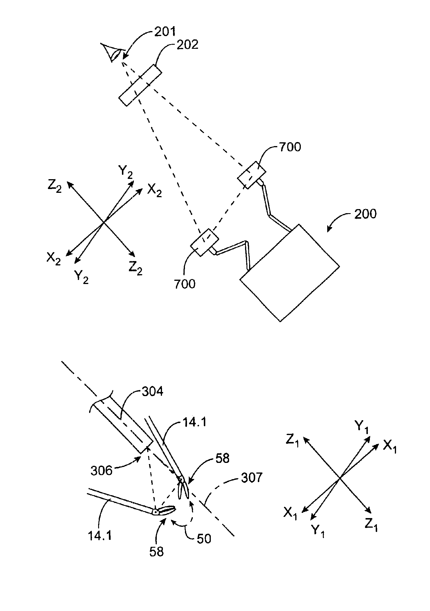
[0012]The present invention provides improved devices, systems, and methods for compensating for friction within powered automatic systems, particularly for telesurgery and other telepresence applications. The invention allows uninhibited manipulation of complex linkages, enhancing the precision and dexterity with which jointed structures can be moved. This enhanced precision is particularly advantageous when applied to the robotic surgical systems now being developed. The friction compensation systems of the present invention address static friction (typically by applying a continuous load in the direction of movement of a joint) and the often more problematic static friction (generally by applying alternating loads in positive and negative joint actuation directions). The invention can accommodate imprecise velocity measurements by applying an oscillating load whenever the joint velocity reading falls within a low velocity range. Preferably, the oscillating load is insufficient to move the joint without additional input, and significantly reduces the break away input required to initiate movement. In the exemplary embodiment, a duty cycle of the oscillating load varies, favoring the apparent direction of movement of a velocity reading. The amplitude of the duty cycle may also vary, typically increasing as the velocity reading approaches zero.
[0015]In the exemplary embodiment, the distribution of the duty cycle between the positive and negative magnitudes is proportional to the component velocity reading positioned within the velocity reading region. The positive and negative duty cycle magnitudes may take a gravity compensation model into account. Such a gravity compensation model may determine a variable gravity compensation force to applied to the component, for example, to artificially balance an unbalanced linkage system. Such a gravity compensated system may further benefit from a determination of a frictional compensation force corresponding to the gravity compensation force in both the positive and negative directions. In other words, in addition to compensating for friction, the method of the present invention may accommodate compensation factors for both friction and gravity, thereby simulating or approximating a friction-free balanced system, significantly enhancing the dexterity of movement which can be accommodated.
[0016]The selection of an appropriate oscillating frequency can significantly enhance friction compensation provided by these methods and systems. Hence, the frequency will preferably be selected so as to be sufficiently slow to enable the actuator (often including an electrical motor and a transmission system such as gears, cables, or the like) to respond to the directing duty cycle signal by applying the desired load, and sufficiently rapid so that the load cannot actually be felt, for example, by physically moving the joint and varying a position of an input master control device held by a surgeon. In other words, the frequency is preferably greater than the mechanical time constraints of the system, yet less than the electrical time constants of an electrical motor used as an actuator. Preferred duty cycle frequency ranges of the exemplary telesurgical system described herein are in a range from about 40 Hz to about 70 Hz, preferably being in a range from about 50 Hz to about 60 Hz. Application of these oscillating loads can facilitate movement of a joint in either a positive or negative direction, particularly when the velocity reading is so low that the system cannot accurately determine whether the system is at rest, moving slowing in a positive direction, or moving slowly in a negative direction. Once velocity measurement readings are high enough (a given measurement reading accuracies) in a positive or negative direction, a continuous (though not necessarily constant) force in the desired direction can overcome the dynamic friction of the joint.
[0018]Preferably, a continuous friction compensation load is applied when the reading is within a second reading range, typically above (either in the positive or negative direction) a minimum value. The continuous load can compensate for friction of the joint, and may vary so as to compensate for gravity when an orientation of the joint changes. The oscillating load similarly compensates for static friction of the joint in the positive and negative directions, at varying points along the load oscillation duty cycle. This method is particularly advantageous for compensating for friction and / or gravity in a joint of the input device for the robotic system, particularly where the oscillating load is less than a static friction of the joint so that the end effector can remain stationary in the hand of the operator.

Problems solved by technology

Preferably, the oscillating load is insufficient to move the joint without additional input, and significantly reduces the break away input required to initiate movement.

Method used


Image

  • Friction compensation in a minimally invasive surgical apparatus
  • Friction compensation in a minimally invasive surgical apparatus
  • Friction compensation in a minimally invasive surgical apparatus

Examples


Embodiment Construction

[0043]This application is related to the following patents and patent applications, the full disclosures of which are incorporated herein by reference: PCT International Application No. PCT / US98 / 19508, entitled “Robotic Apparatus”, filed on Sep. 18, 1998; U.S. Application Ser. No. 60 / 111,713, entitled “Surgical Robotic Tools, Data Architecture, and Use”, filed on Dec. 8, 1998; U.S. Application Ser. No. 60 / 111,711, entitled “Image Shifting for a Telerobotic System”, filed on Dec. 8, 1998; U.S. Application Ser. No. 60 / 111,714, entitled “Stereo Viewer System for Use in Telerobotic System”, filed on Dec. 8, 1998; U.S. Application Ser. No. 60 / 111,710, entitled “Master Having Redundant Degrees of Freedom”, filed Dec. 8, 1998; and U.S. Pat. No. 5,808,665, entitled “Endoscopic Surgical Instrument and Method for Use”, issued on Sep. 15, 1998; the full disclosures of which are incorporated herein by reference.

[0044]It is to be appreciated that although the method and control system of the inv...


PUM


Abstract

Devices, systems, and methods for compensate for friction within powered automatic systems, particularly for telesurgery and other telepresence applications. Dynamic friction compensation may comprise applying a continuous load in the direction of movement of a joint, and static friction compensation may comprise applying alternating loads in positive and negative joint actuation directions whenever the joint velocity reading falls within a low velocity range.

Description

CROSS-REFERENCES TO RELATED APPLICATIONS[0001]This is a divisional patent application which claims priority from U.S. patent application Ser. No. 09 / 287,513 filed Apr. 7, 1999 now U.S. Pat. No. 6,565,554, the full disclosure of which is incorporated herein by reference.BACKGROUND OF THE INVENTION[0002]The present invention is generally related to improved robotic devices and methods, particularly for telesurgery.[0003]Minimally invasive medical techniques are aimed at reducing the amount of extraneous tissue which is damaged during diagnostic or surgical procedures, thereby reducing patient recovery time, discomfort, and deleterious side effects. Many surgeries are performed each year in the United States. A significant amount of these surgeries can potentially be performed in a minimally invasive manner. However, only a relatively small percentage of surgeries currently use these techniques due to limitations in minimally invasive surgical instruments and techniques and the additio...

Claims


Application Information

Patent Timeline
Patent Type & Authority Patents(United States)
IPC IPC(8): A61B19/00
CPCA61B19/22A61B19/2203A61B19/46A61B17/00234A61B19/5212A61B2019/2223A61B2019/2234A61B2017/00477A61B2019/223A61B34/37A61B34/30A61B34/35A61B34/70A61B90/06A61B90/361A61B2034/305
Inventor NIEMEYER, GUNTER D.
Owner INTUITIVE SURGICAL OPERATIONS INC
Why Eureka
Try Eureka