
Solid-state lamps with light guide and photoluminescence material

Inactive Publication Date: 2012-06-07
INTEMATIX
View PDF7 Cites 76 Cited by
  • Summary
  • Abstract
  • Description
  • Claims
  • Application Information

AI Technical Summary

Benefits of technology

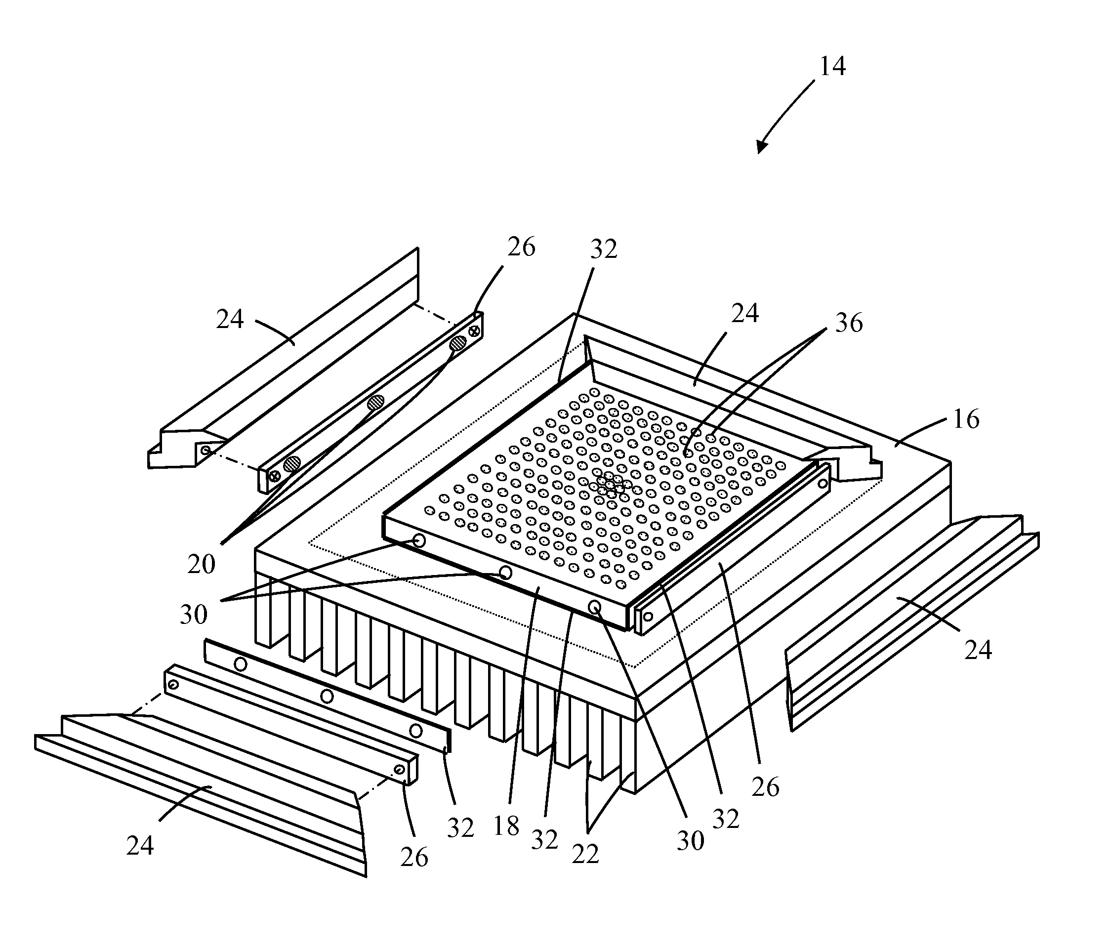
[0013]Embodiments of the invention concern solid-state lamps comprising a light guiding medium (light guide) having on at least one surface a pattern of light extracting features. In some embodiments, the invention is characterized by the light extracting features comprising at least one photoluminescence (e.g., phosphor) material that is deposited, typically by printing, as a pattern of features directly on a face of the light guide. In this patent specification “directly” means in contact with the face of the light guide and without the presence of any intervening layers or an air gap. Since the phosphor features provide both the mechanisms for extracting light from the light guide and converting light to different wavelength this eliminates the need for additional light extracting or scattering features. Since the phosphor is deposited directly on the light guide surface this eliminates the optical losses otherwise associated with light traveling through the light guide-air and air-phosphor interfaces thereby increasing the optical efficiency of the lamp.
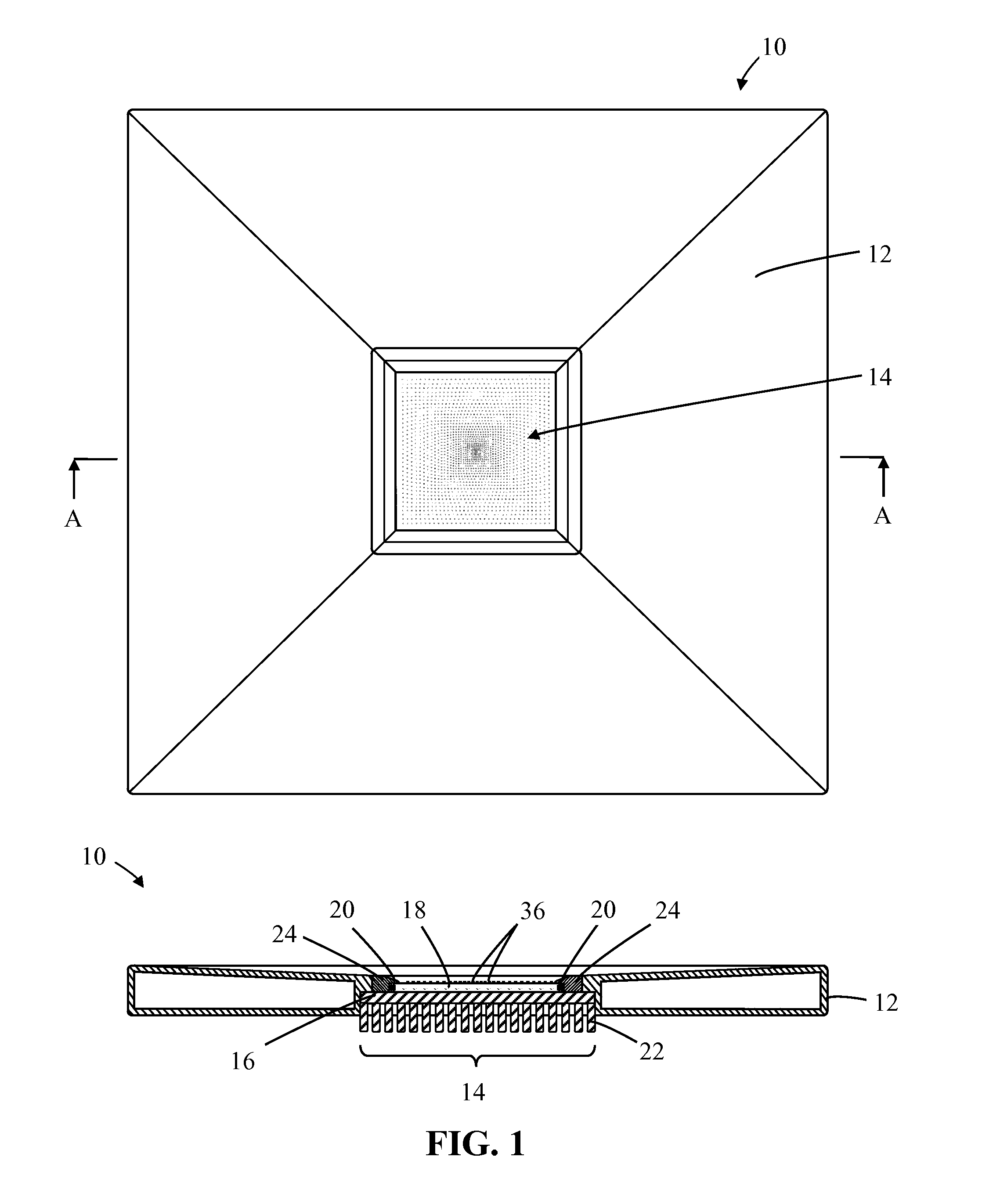
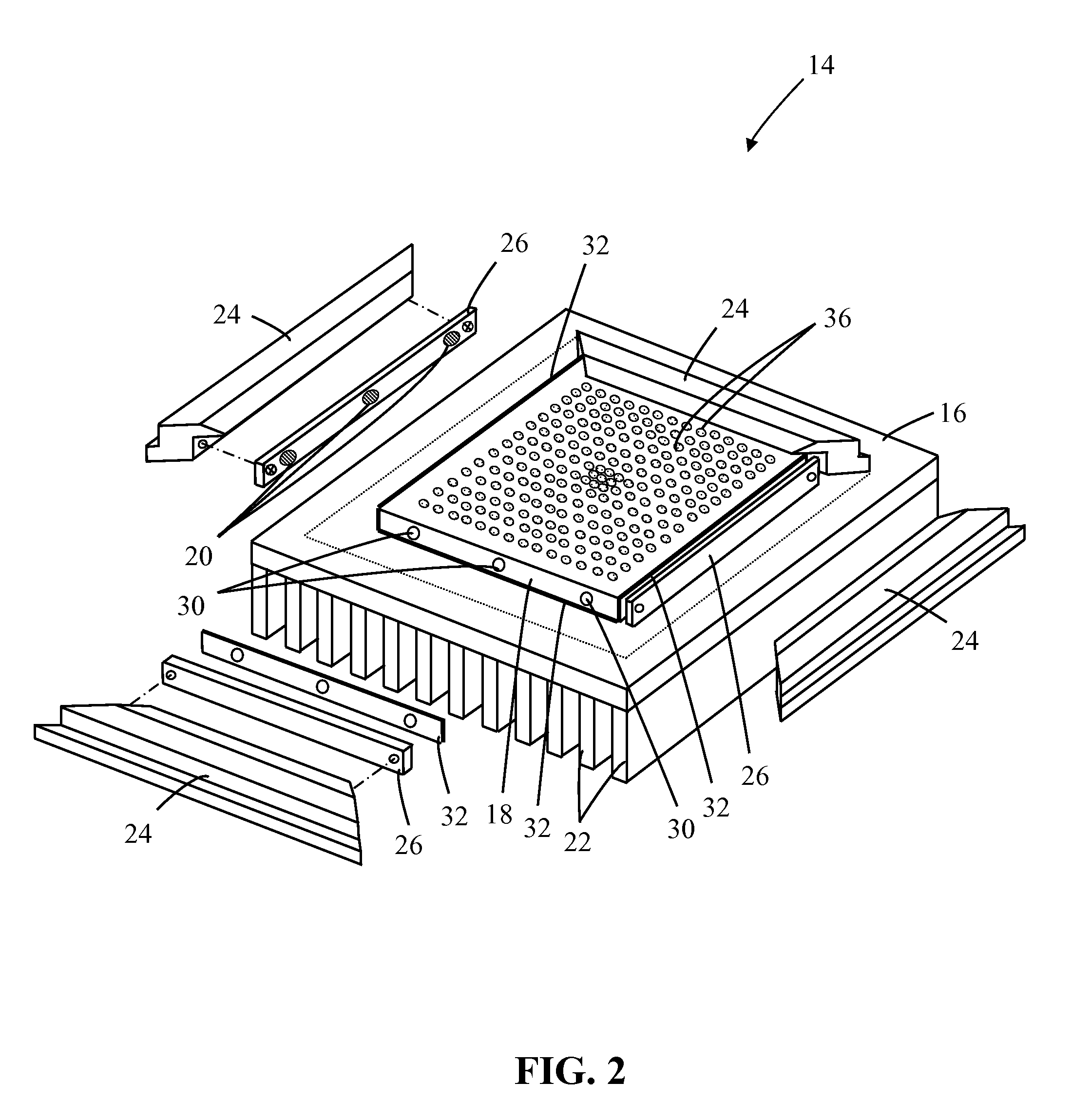
[0022]In some embodiments, the solid-state light emitters which typically comprise LEDs are configured as an array with their emission axes substantially perpendicular to the plane of the light guide. The light can be coupled into a rear face (i.e. the face opposite the front light emitting face) of the light guide. The light guide can comprise a planar configuration (e.g., having a circular or elliptical disc shape, rectangular plane shape, square plane shape, triangular or other polygonal shapes) with the LEDs being circumferentially space around the edge of the light guide. To increase the uniformity of light emission the pattern of light extracting features can comprise concentric patterns of features in which the spacing between feature patterns decreases towards the center of the light guide. In addition, the size of the features can additionally increase towards the center of the light guide. The features can comprise can comprise lines; substantially circular features; substantially elliptical features; substantially square features; substantially rectangular features; substantially triangular features; substantially hexagonal features, substantially polygonal shaped features or combinations thereof. In one arrangement the features can comprise circular dots. The pattern of the light extracting features can be configured to minimize variation in the emission intensity over the entire face of the light guide.
[0024]The edge of the light guide can be configured such that light emitted by the LEDs are redirected inwardly through the light guide. For example, the edge of the light guide can be configured to be curved or rolled from the rear face to the front face, and can be covered with a light reflective material such as chromium, aluminum or a light reflective paper or plastics material. The edge of the light guide can also be configured to slant inwardly from the rear face to the front face as a beveled edge that is covered with a light reflective material such as chromium, aluminum or a light reflective paper or plastics material. It will be appreciated that the edge(s) of the light guide can be configured with other geometries to ensure that light that is coupled into the face is redirected by the edge(s) into the volume of the light guide. The light reflective edge(s) can be configured to prevent light being emitted from the front face of the light guide that would otherwise be transmitted directly through the guide.
[0025]Locating the LEDs around the periphery of the light guide provides numerous advantages, such as heat management advantages and also minimizes component count in the optics, heat sink and electronics, thereby minimizing manufacturing costs.
[0026]Some embodiments provide an arrangement using non-remote-phosphor lamps that employ white LEDs, where the white LEDs are formed using powdered phosphor material that is mixed with a light transmissive liquid binder, typically a silicone or epoxy, and where the mixture is applied directly to the light emitting surface of the LED die such that the LED die is encapsulated with phosphor material. Since the phosphor material is not remote to the LED, this approach does not need phosphor materials deposited onto the light guide to generate white light. However, light extracting features will still be provided onto at least one surface of the light guide to allow the white light generated by the white LEDS to emit from the light guide. These light extracting features are configured to cause a difference in the refractive properties of the light extracting features as compared to the light guide itself. This allows white light emitted from the LEDs to escape the light guide if directed at the light extracting features at appropriate emission angles.
[0028]Another embodiment of the LED lamp is generally configured as a cylindrical structure, having a lower body that is formed as a linearly extending partial-cylindrical shape between two circular end units. The body can be of a hollow or solid construction and can be fabricated from any suitable sheet material, such as sheet metal, cast metal or a molded plastics material. A light guide is also formed as a linearly extending partial-cylindrical shape between the two circular end units. LEDs are mounted in the end units, where each LED is configured with its emission axis parallel with the plane of the light guide. The pattern of phosphors on the light guide can comprise parallel patterns of dots in which the spacing between parallel patterns decreases towards the center of the light guide. Moreover, the size of the dots can additionally increase towards the center of the light guide. Typically the phosphor pattern is configured to minimize variation in the emission intensity over the entire face of the light guide.

Problems solved by technology

For a phosphor encapsulated LED the high operating temperature of the LED can degrade the phosphor resulting in reduced optical efficiency, a color shift in the emitted light and a shortened lifetime.
Since an LED approximates to a point source this can result in hot spots corresponding to the location of the LED(s).
Whilst the use of a diffuser can improve emission uniformity it reduces the overall emission radiance and luminous efficacy of the device.
However the inventor has discovered that having an air gap between the light guide and phosphor layer lowers the absorption efficiency of blue light by the phosphor material resulting in a lower overall optical efficiency.

Method used


Image

  • Solid-state lamps with light guide and photoluminescence material
  • Solid-state lamps with light guide and photoluminescence material
  • Solid-state lamps with light guide and photoluminescence material

Examples


Embodiment Construction

[0052]Embodiments of the invention concern solid-state lamps comprising a light guiding medium (light guide or waveguide) having at least one light emitting surface in which light is coupled into the medium such that it is guided, by internal reflection, throughout the volume of the medium. The light guide includes a pattern of light extracting features on at least one surface and / or face, from which light is extracted from the light guide and emitted as the final light emission product.

[0053]The light extracting features may be integrally formed onto the light guide material, e.g. by molding certain structures into the light guide from which light maybe extracted from the light guide. In addition, the light extracting features may be formed by treating the surface of the light guide at specified locations. For example, the surface of the light guide may be treated by removing materials from the light guide surface, modifying the property of the light guide material, or depositing a...


PUM


Abstract

A solid-state lamp comprises a light guide having at least one light emitting face and at least one solid-state light source (LED) configured to couple light into the light guide. The lamp further comprises a pattern of light extracting features for promoting emission of light from the light guide wherein the pattern of light extracting features is formed on at least one face of the light guide.

Description

CROSS-REFERENCE TO RELATED APPLICATIONS[0001]This application claims the benefit of priority to U.S. Provisional Application No. 61 / 419,080, filed Dec. 2, 2010, entitled “Solid-state lamps with light guide and photoluminescent material” the specification and drawings of which are incorporated herein by reference in its entirety.BACKGROUND OF THE INVENTION[0002]1. Field of the Invention[0003]This invention relates to solid-state lamps with a light guide and photoluminescence material. In particular, although not exclusively, the invention concerns lamps based on LEDs (Light Emitting Diodes).[0004]2. Description of the Related Art[0005]White light emitting LEDs (“white LEDs”) are known and are a relatively recent innovation. It was not until LEDs emitting in the blue / ultraviolet part of the electromagnetic spectrum were developed that it became practical to develop white light sources based on LEDs. As taught, for example in U.S. Pat. No. 5,998,925, white LEDs include one or more phot...

Claims


Application Information

Patent Timeline
IPC IPC(8): F21V13/02F21V8/00F21V9/16
CPCF21V13/02G02B6/0068F21Y2103/003G02B6/0061F21V9/16F21Y2105/00F21Y2101/02G02B6/0043F21V13/08F21Y2103/10F21Y2103/33F21Y2115/10F21V9/32F21V9/45F21V9/30
Inventor YANG, HAITAOLI, YI-QUNCOLLIER, IAN
Owner INTEMATIX
Learn More