
DSP-based comparison-division type optical fiber high-precision frequency measurement sensor

A high-precision, sensor technology, used in linear/angular velocity measurement, velocity/acceleration/shock measurement, instruments, etc., to solve problems such as unstable light source power, inability to achieve high-precision micro-frequency measurement, and inability to fully respond to optical fiber signals. , to achieve accurate and reliable frequency measurement results

Inactive Publication Date: 2017-08-22
GUANGDONG KINGPOINT DATA SCI & TECH CO LTD
View PDF6 Cites 1 Cited by
  • Summary
  • Abstract
  • Description
  • Claims
  • Application Information

AI Technical Summary

Problems solved by technology

However, due to the loss of different degrees of light waves in the transmission process of the optical fiber, some light sources will be coupled into the optical fiber, which will cause the instability of the power of the light source and make the optical fiber signal unable to fully reflect the rotational frequency of the rotor to be tested. signal, it is impossible to achieve high-precision micro-frequency measurement, so there is an urgent need for a sensor that can achieve high-precision measurement

Method used


Image

  • DSP-based comparison-division type optical fiber high-precision frequency measurement sensor
  • DSP-based comparison-division type optical fiber high-precision frequency measurement sensor
  • DSP-based comparison-division type optical fiber high-precision frequency measurement sensor

Examples


Embodiment Construction

[0018] The present invention is described in further detail below by specific embodiments:

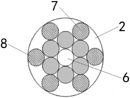
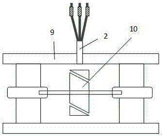
[0019] The reference signs in the accompanying drawings include: laser light source 1, fiber probe 2, preprocessing circuit 3, DSP chip 4, host computer 5, transmitting fiber 6, first group of receiving fibers 7, second group of receiving fibers 8, Rotor top casing 9 and rotor blades 10 to be tested.

[0020] like figure 1 The shown one DSP-based ratio-division fiber-optic high-precision frequency measurement sensor includes: a laser light source 1 that emits laser light to a fiber-optic probe 2;

[0021] Fiber probe 2, such as figure 2 As shown, it includes a transmitting optical fiber 6 and two groups of receiving optical fibers, each group contains six optical fibers, the first group of receiving optical fibers 7 is distributed on the outside of the transmitting optical fiber 6, and the second group of receiving optical fibers 8 is distributed in the first group of receiving opti...


PUM


Abstract

The invention relates to the technical field of rotor rotational frequency measurement, and provides a DSP-based comparison-division type optical fiber high-precision frequency measurement sensor capable of realizing high-precision measurement. The sensor comprises a laser source, an optical fiber probe, a prepositioned circuit and a DSP chip, wherein the laser source is used for emitting laser to the optical fiber probe; the optical fiber probe comprises an emitting optical fiber and two groups of receiving optical fibers, the emitting optical fiber emits received laser onto a rotor blade to be measured, and the receiving optical fibers are used for receiving reflected laser reflected by the rotor blade to be measured; the prepositioned circuit is used for receiving two groups of reflected laser transmitted by the optical fiber probe, and calculating the two groups of laser to obtain a voltage real-time ratio; and the DSP chip is used for processing the voltage real-time ratio to obtain a voltage frequency, and subjecting the voltage frequency to linear transformation to obtain a rotational speed.

Description

technical field [0001] The invention relates to the technical field of rotor rotation frequency measurement, in particular to an optical fiber high-precision frequency measurement sensor. Background technique [0002] An object without its own axis of rotation can be regarded as a rotor when a rigid connection or an additional axis is used, and the rotor, as the rotating part of the motor, is an important part. Usually the rotor consists of a rotating shaft, a rotor core and a rotor winding. The rotor rotation frequency is one of the most important parameters in social life and production practice. [0003] In order to measure the frequency of the rotor, various frequency measuring instruments have appeared on the market. In order to adapt to the high voltage and strong electromagnetic interference environment, fiber optic sensors with good insulation characteristics and anti-interference ability are usually used for measurement. However, due to the different degrees of lo...

Claims


Application Information

Patent Timeline
Patent Type & Authority Applications(China)
IPC IPC(8): G01D21/00G01P3/486
CPCG01D21/00G01P3/486
Inventor 侯大勇李青海简宋全邹立斌
Owner GUANGDONG KINGPOINT DATA SCI & TECH CO LTD
Learn More