Heat sink with heat pipe and base fins

a heat sink and heat pipe technology, applied in the direction of insulated conductors, cables, semiconductor/solid-state device details, etc., can solve the problems of inefficiency, complex design of the base-pipe interface, failure to operate the electronic component, etc., to achieve efficient dissipation of heat from one or more heat-generating components, reduce the effect of heat loss

Inactive Publication Date: 2005-05-17
HEWLETT-PACKARD ENTERPRISE DEV LP
View PDF24 Cites 35 Cited by
  • Summary
  • Abstract
  • Description
  • Claims
  • Application Information

AI Technical Summary

Benefits of technology

[0008]Such a heat sink can dissipate heat from one or more heat-generating components more efficiently because of the heat pipe and the fins working in tandem to transfer heat from the heat-generating source. A heat pipe is a device that provides an efficient way of cooling heat-generating components as heat is transferred from the heat-generating component by means of a liquid / gas evaporation / condensation cycle. Additionally, fins attached to the base of the heat sink provide even more surface area for dissipating heat from a heat source. The heat pipe and fins combination transfers heat from heat-generating components more efficiently than either a heat pipe alone or fins alone.

Problems solved by technology

As the generated heat increases above a critical temperature, a failure can occur in the operation of the electronic component.
Furthermore, sometimes the bases of these heat pipes are rectangular and the heat pipe itself is round so the base-pipe interface may have a complex design.
This, however, is less efficient due to the added thermal resistance of the base and the material (e.g. adhesive) used to attach the heat pipe to the base.
Yet another problem with a heat pipe is that it can fail by forming a leak such that the vacuum pressure decreases, possibly by corrosion of the wicking material, contamination of the fluid, etc.
As a result, when a heat pipe fails, it becomes less effective at transferring heat from the electronic component to the ambient environment and thus becomes less effective in cooling the component.
If the failure of the heat pipe is severe enough, the component can overheat and fail.

Method used


Image

  • Heat sink with heat pipe and base fins
  • Heat sink with heat pipe and base fins
  • Heat sink with heat pipe and base fins

Examples


Embodiment Construction

[0015]The following discussion is presented to enable one skilled in the art to make and use the invention. Various modifications to the disclosed embodiments will be readily apparent to those skilled in the art, and the generic principles herein may be applied to other embodiments and applications without departing from the spirit and scope of the present invention as defined by the listed claims. Thus, the present invention is not intended to be limited to the embodiments shown, but is to be accorded the widest scope consistent with the principles and features disclosed herein.

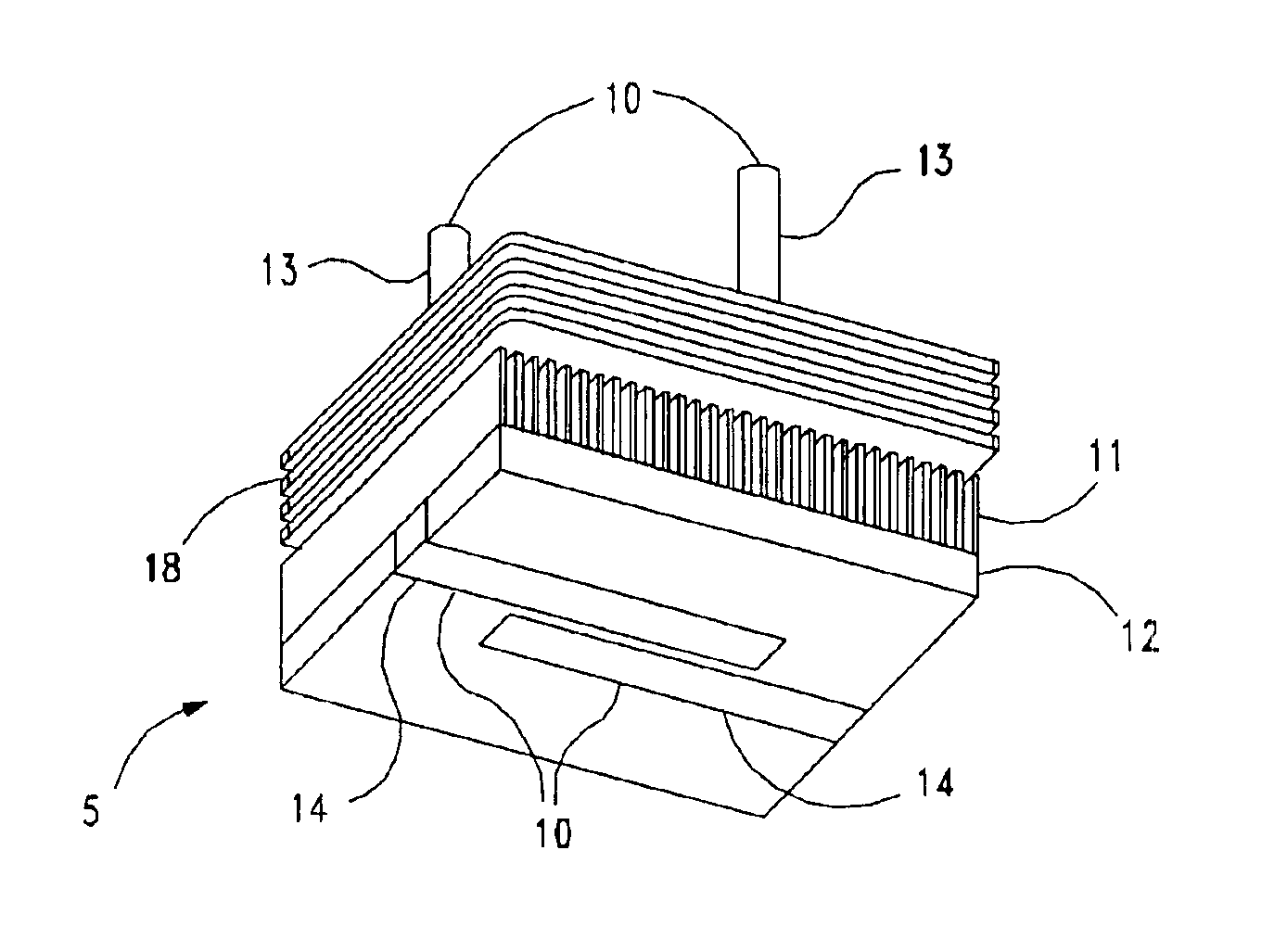
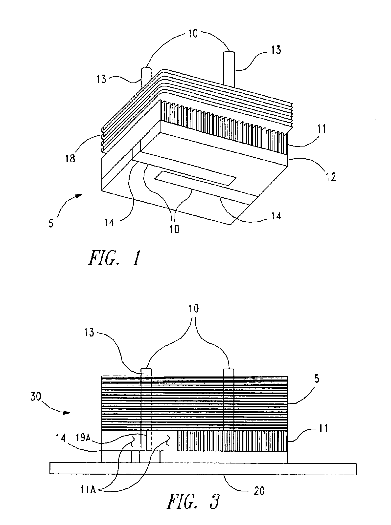
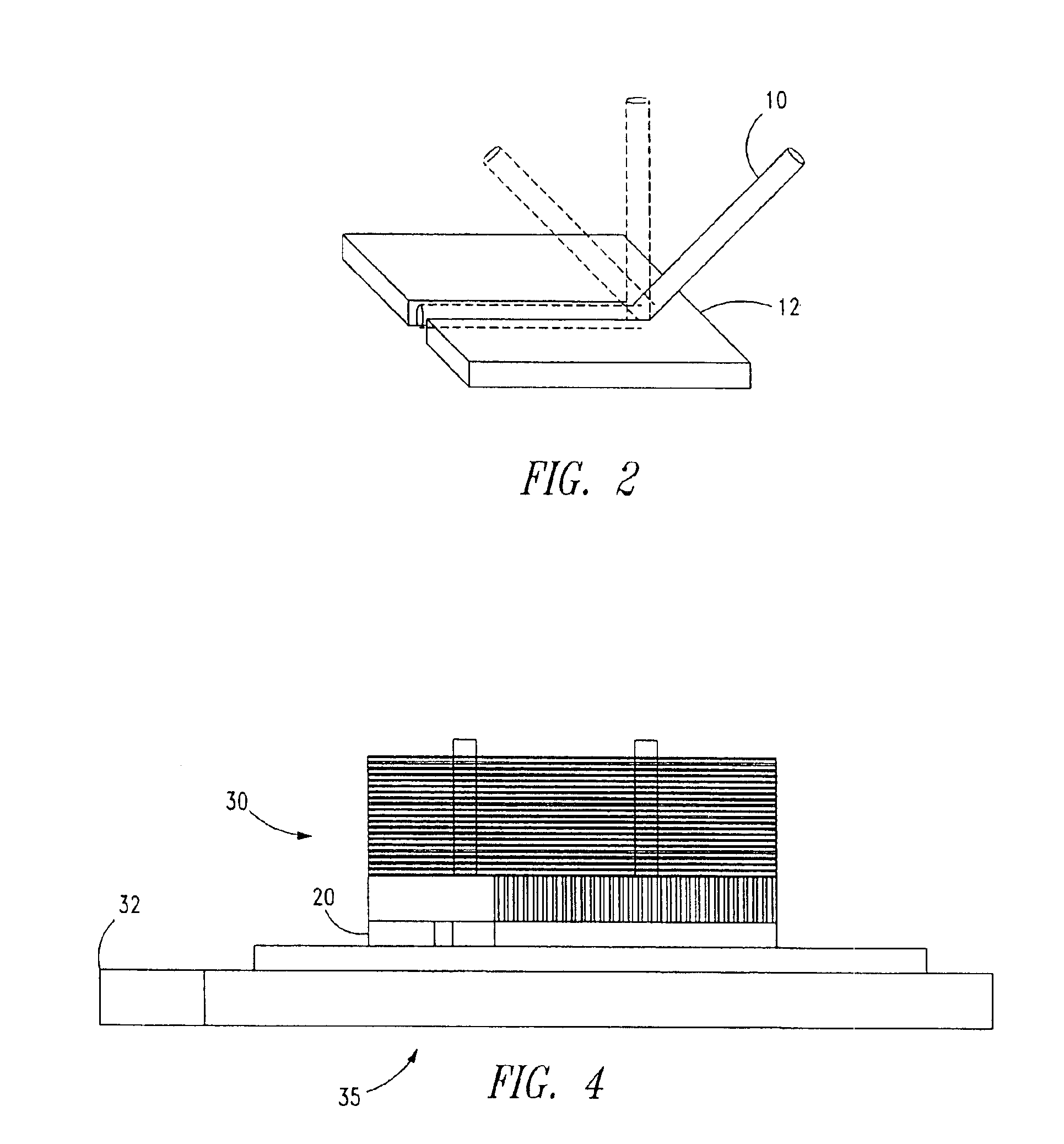
[0016]FIG. 1 is an isometric view of a heat sink 5 according to an embodiment of the invention. The heat sink 5 comprises multiple heat pipes although alternative embodiments only include one heat pipe. According to this embodiment, there are two heat pipes 10 attached to a base 12. A heat pipe 10 is attached to the base 12 in any conventional manner, including adhesive, form-fitted (“snap-on”), harnessed, b...


PUM


Abstract

A heat sink includes at least one heat pipe attached to a base having a substantially flat region for interfacing with an electronic component. Additionally, the heat sink comprises fins attached to the base and at least one heat pipe. The fins and the base may be integral with or attached to each other. Such a heat sink can dissipate heat from one or more electronic components more efficiently as the heat pipe coupled with the fins attached to the base provide alternate heat transfer paths for heat generated by electronic components.

Description

CROSS-RELATED APPLICATIONS[0001]This application is related to U.S. patent application Ser. No. 10 / 246,343, for HEATSINK WITH HEAT PIPE IN DIRECT CONTACT WITH COMPONENT and U.S. patent application Ser. No. 10 / 246,299, for HEATSINK WITH ANGLED HEAT PIPE, which were filed concurrently on Sep. 17, 2002, and which are hereby incorporated by reference in their entirety.BACKGROUND OF THE INVENTION[0002]It is well known that an electronic component generates heat as it operates. As the generated heat increases above a critical temperature, a failure can occur in the operation of the electronic component. Therefore, the excess heat must be dissipated to prevent such failures.[0003]One type of heat sink used to dissipate heat includes a heat pipe. A heat pipe is a vacuum-sealed pipe that is filled with a heat-transfer liquid, such as water, and has the interior wall of the heat pipe covered with a wicking material. As the electronic component heats up, the “hot” end of the heat pipe closest ...

Claims


Application Information

Patent Timeline
Patent Type & Authority Patents(United States)
IPC IPC(8): F28F3/00F28F3/02F28F1/32F28D15/02H01L23/427H01L23/34H05K7/20
CPCF28D15/02F28F1/32F28F3/02H01L23/427F21V29/006H01L2924/3011H01L2924/0002H01L2924/00F28D15/0275F21V29/51F21V29/74
Inventor MALONE, CHRISTOPHER G.
Owner HEWLETT-PACKARD ENTERPRISE DEV LP
Why Eureka
Try Eureka