Impingement cooling of turbine blades or vanes

a technology of turbine blades and vanes, which is applied in the direction of liquid fuel engines, vessel construction, marine propulsion, etc., can solve the problems of blade or vanes being damaged, disoriented, etc., and achieve the effect of facilitating thermodynamically efficient aerofoils and gas turbine components

Inactive Publication Date: 2014-08-07
SIEMENS AG
View PDF4 Cites 35 Cited by
  • Summary
  • Abstract
  • Description
  • Claims
  • Application Information

AI Technical Summary

Benefits of technology

[0008]It is a first objective to provide an advantageous aerofoil-shaped turbine assembly such as a turbine rotor blade or a stator vane in which the above-mentioned shortcomings can be mitigated, and especially a more thermo-dynamically efficient aerofoil and gas turbine component is facilitated.

Problems solved by technology

The effect of temperature on the turbine blades and / or stator vanes can be detrimental to the efficient operation of the turbine and can, in extreme circumstances, lead to distortion and possible failure of the blade or vane.
Problems arise due to a complex and time consuming assembly process and fault positioning of the impingement devices.

Method used


Image

  • Impingement cooling of turbine blades or vanes
  • Impingement cooling of turbine blades or vanes
  • Impingement cooling of turbine blades or vanes

Examples


Embodiment Construction

[0055]In the present description, reference will only be made to a vane, for the sake of simplicity, but it is to be understood that the invention is applicable to both blades and vanes of a turbine.

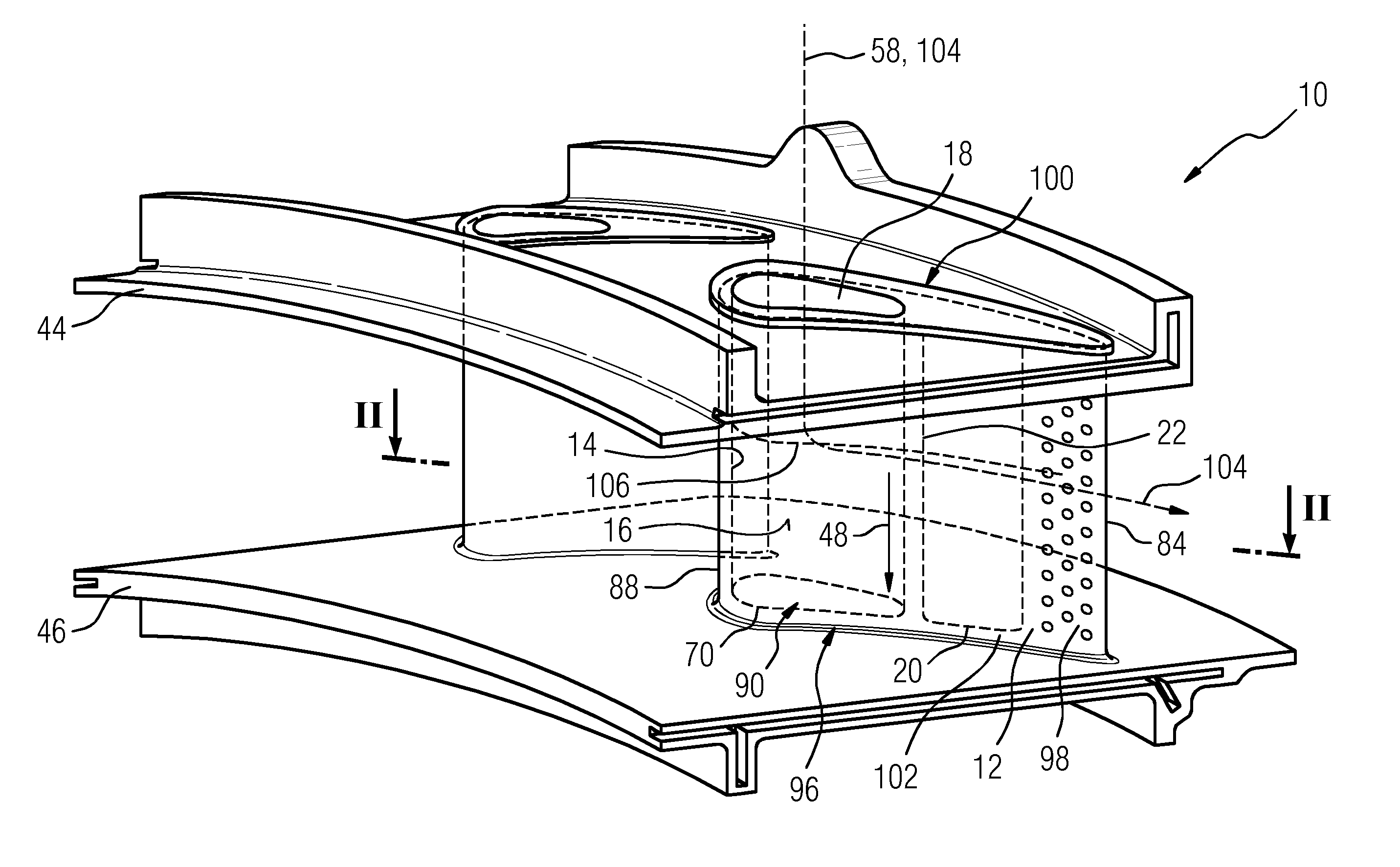
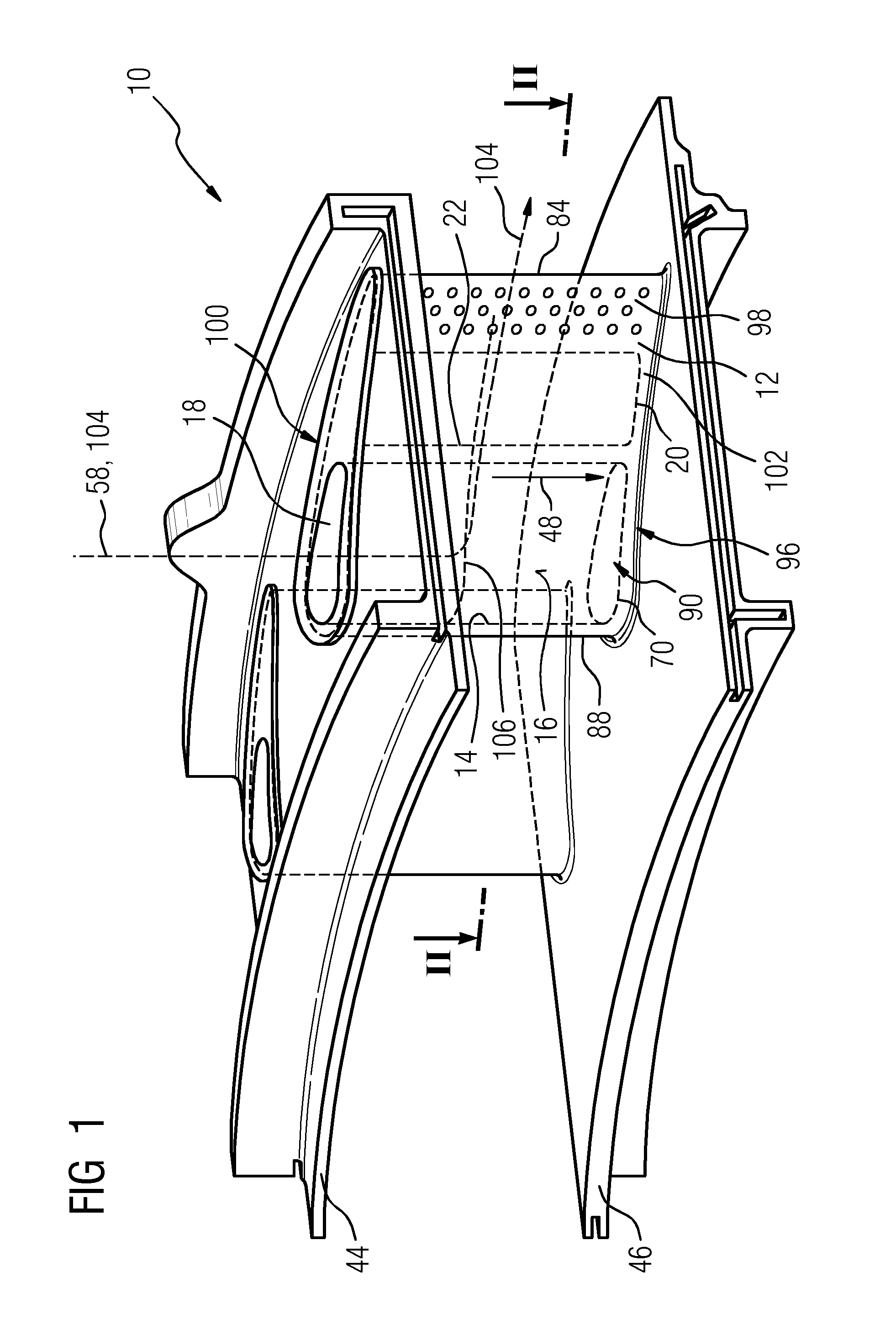
[0056]FIG. 1 shows in a perspective view a turbine assembly 10, particularly a gas turbine assembly. The turbine assembly 10 comprises a basically hollow aerofoil 12, embodied as a vane 90, having a cavity 14 with an inner wall 16, wherein the latter builds an outer perimeter of the cavity 14. Moreover, the aerofoil 12 has an aperture 18 providing access to the cavity 14. Further, the aerofoil 12 has two cooling regions, specifically, an impingement cooling region 96 and a fin-pin / pedestal cooling region 98. The former is located at a leading edge 88 as well as in a middle section 100 and the latter at a trailing edge 84 of the aerofoil 12. An outer platform 44 and an inner platform 46 are arranged perpendicular to a span wise direction 48 of the hollow aerofoil 12 and are positioned on ...


PUM

PropertyMeasurementUnit
angleaaaaaaaaaa
angleaaaaaaaaaa
angleaaaaaaaaaa

Abstract

The present invention relates to a turbine assembly with a basically hollow aerofoil, having at least a cavity with an inner wall and having at least an aperture providing access to the cavity, and at least a first impingement device arrangeable within the cavity. The at least first impingement device is self-locking, resilient and preloadable and has at least one locking element to lock the at least first impingement device in place in the cavity via a force fit between the at least one locking element and the inner wall of the cavity wherein the locking element of the at least first impingement device is embodied as a protrusion extending in an assembled state of the at least first impingement device in the cavity basically perpendicular to a surface of a side wall of the at least first impingement device in a direction towards the inner wall.

Description

CROSS REFERENCE TO RELATED APPLICATIONS[0001]This application is the US National Stage of International Application No. PCT / EP2012 / 067138 filed Sep. 3, 2012, and claims the benefit thereof. The International Application claims the benefit of European Application No. EP11182554 filed Sep. 23, 2011. All of the applications are incorporated by reference herein in their entirety.FIELD OF THE INVENTION[0002]The present invention relates to an aerofoil-shaped turbine assembly such as turbine rotor blades or stator vanes. The present invention further relates to a method for assembling an impingement device in such assemblies.BACKGROUND TO THE INVENTION[0003]Modern turbines often operate at extremely high temperatures. The effect of temperature on the turbine blades and / or stator vanes can be detrimental to the efficient operation of the turbine and can, in extreme circumstances, lead to distortion and possible failure of the blade or vane. In order to overcome this risk, high temperature ...

Claims


Application Information

Patent Timeline
Patent Type & Authority Applications(United States)
IPC IPC(8): F01D5/18B23P11/02
CPCF01D5/188B23P2700/06B23P11/02F01D5/189F05D2260/201F05D2230/60Y10T29/49872
Inventor NILSSON, ULF
Owner SIEMENS AG
Why Eureka
Try Eureka