Transfer robot

a robot and robot technology, applied in the field of robots, can solve the problems of increasing the transfer speed of robots, high cost and heavy weight of products, and complex wiring and actuators, and achieve the effect of simple construction and efficient work transfer operation

Active Publication Date: 2005-06-02
DAIHEN CORP
View PDF4 Cites 30 Cited by
  • Summary
  • Abstract
  • Description
  • Claims
  • Application Information

AI Technical Summary

Benefits of technology

[0027] This arrangement makes it possible to perform efficient work transfer operation in a manner such that one hand receives a processed work from one process chamber, while the other hand delivers a different work to the process chamber for another cycle of process.
[0028] As des...

Problems solved by technology

If the hand were provided with e.g. a movable clamp mechanism for enabling operation in the vacuum environment, the wiring and the actuator would become extremely complex in construction, and this would result in high cost and heavy weight for the products.
These limitations make it i...

Method used


Image

  • Transfer robot
  • Transfer robot
  • Transfer robot

Examples


Embodiment Construction

[0048] Preferred embodiments of the present invention will be described below with reference to FIG. 1 through FIG. 14.

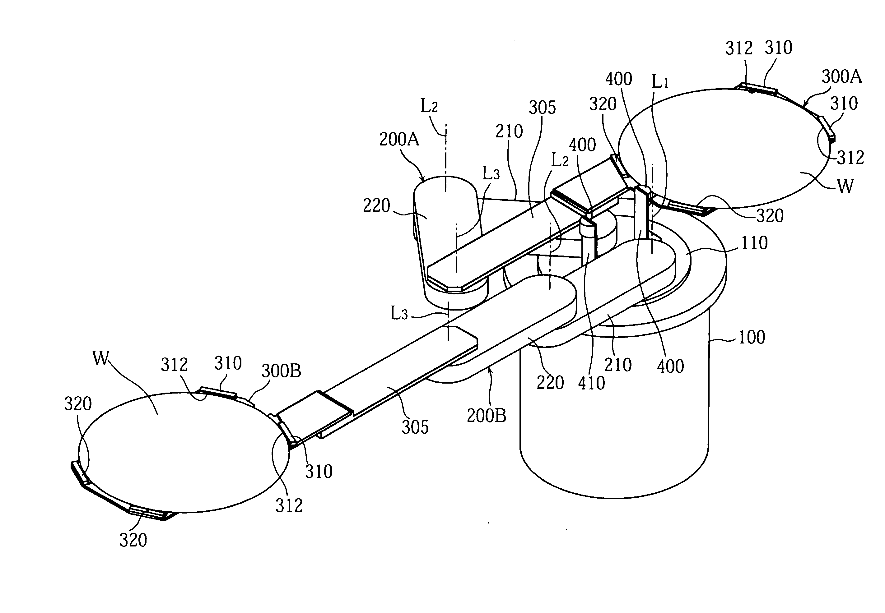
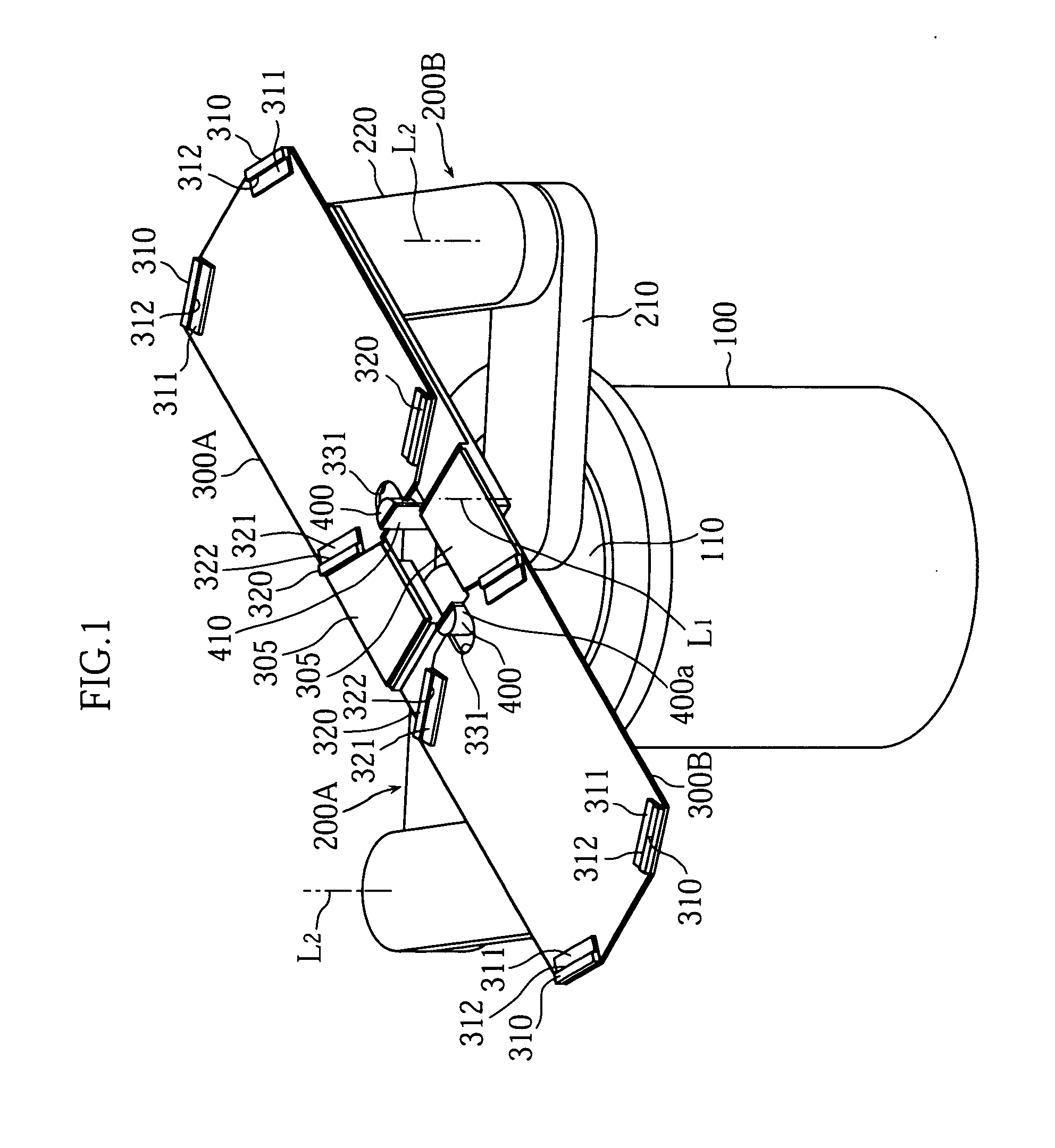
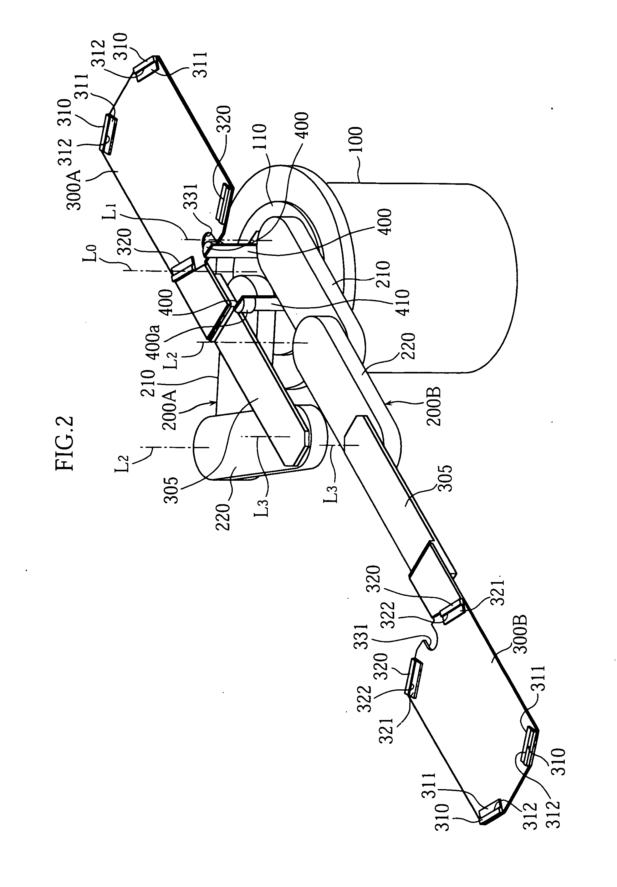
[0049]FIG. 1 through FIG. 9 show a transfer robot according to a first embodiment of the present invention. As seen from FIG. 1, FIG. 2 and FIG. 5 in particular, the transfer robot includes a cylindrical base 100, a swivel base 110 which is incorporated in the cylindrical base 100 and is pivotable about a vertical swivel axis L0, a pair of linear transfer mechanisms 200A, 200B mounted on the swivel base 110, and hands 300A, 300B which are supported by the linear transfer mechanisms 200A, 200B respectively.

[0050] Each of the linear transfer mechanisms 200A, 200B includes a first arm 210 which is pivotable with respect to the swivel base 110 about a vertical first axis L1, a second arm 220 which is pivotable about a second axis L2 that is vertical with respect to a tip of the first arm 210. The second arm 220 has a tip provided with a bracket 305 which is pivotable ...


PUM


Abstract

A transfer robot includes a swivel base pivotable about a vertical axis, a hand for holding a plate-like work placed thereon, and a linear transfer mechanism supporting the hand and provided on the swivel base. The transfer mechanism is designed to move the hand forward and backward along a horizontal linear path. The hand is provided with a front stopper for checking a front edge of the work. The swivel base is provided with a work holder contacting a rear edge of the work when the hand is moved to a retracted position on the linear path.

Description

BACKGROUND OF THE INVENTION [0001] 1. Field of the Invention [0002] The present invention relates to a transfer robot. More specifically, the present invention relates to a transfer robot for transporting a thin plate-like work, such as a semiconductor wafer, along a straight path. [0003] 2. Description of the Related Art [0004] Among many transfer robots, there is a group of transfer robots which have a mechanism for moving their hands along straight paths (linear transfer mechanism). These robots are simpler in construction and cheaper than the so-called jointed-arm robots, and are used widely in e.g. manufacturing process of semiconductor devices, for transportation of thin, plate-like works such as wafers into and out of different process chambers. [0005] Such transfer robots are disclosed in JP-A-2002-531942 and JP-A-2003-142572, for example. The transfer robots disclosed in these documents generally have a basic construction as shown in FIG. 15 through FIG. 17 of the present a...

Claims


Application Information

Patent Timeline
IPC IPC(8): B25J15/08B65G49/07B25J9/06B66C23/00H01L21/677H01L21/68H01L21/687
CPCB25J9/009Y10T74/20305H01L21/68707H01L21/67742
Inventor OGAWA, HIRONORIUNO, SAKIKO
Owner DAIHEN CORP
Why Eureka
Try Eureka