Medical Manipulator

a technology of manipulators and manipulators, applied in the field of medical manipulators, can solve the problems of easy complex structure of medical manipulators, and achieve the effect of increasing the complexity of the structure of the medical manipulator and high degree of freedom

Active Publication Date: 2015-01-22
KARL STORZ GMBH & CO KG
View PDF2 Cites 250 Cited by
  • Summary
  • Abstract
  • Description
  • Claims
  • Application Information

AI Technical Summary

Benefits of technology

[0005]Incidentally, in the medical manipulator, it is desirable for the distal end working unit including the end effector to have a high degree of freedom and to have a movable range that is as wide as possible. For example, if the range of rotation of the rolling operation of the distal end working unit were unlimited, such a feature could be expected to contribute to the smooth performance of procedures such as ligation or the like. On the other hand, as the degree of freedom of the distal end working unit is increased, it is easy for the structure of the medical manipulator to become complex.
[0006]The present invention has been devised while taking into consideration the aforementioned problems, and has the object of providing a medical manipulator, which is equipped with a distal end working unit having a high degree of freedom, without increasing the complexity of the structure of the medical manipulator.
[0008]According to the structure of the present invention as described above, since the operating means (e.g., a drive member for opening and closing or rotating the end effector, wires for supplying electricity to the end effector, etc.) can be arranged substantially in the center of the distal end working unit by having the distal end side rotating body be of a hollow shape, a structure can be adopted in which the range of rotation of the rolling operation of the distal end working unit is unlimited. Further, since the rotating support cylinder is arranged not on the inside of the distal end side rotating body but on the outer side thereof, the hollow portion of the distal end side rotating body can suitably ensure an arrangement space for the operating means, together with enabling the structure of the distal end working unit to be simplified. Accordingly, a medical manipulator is provided, which is equipped with the distal end working unit having a high degree of freedom, without increasing the complexity of the structure of the medical manipulator.
[0010]According to the above structure, the arrangement space for the operating means can easily be assured in the interior of the joint.
[0012]According to the above structure, the plural segments are connected in the circumferential direction, thereby constituting the rotating support cylinder that supports the distal end side rotating body on an inner circumferential portion thereof. Consequently, during assembly of the distal end working unit, by mutually joining the plurality of segments by welding or the like so as to surround the distal end side rotating body with the plural segments, a configuration can easily be constructed in which the rotating body is arranged inside of the segments, and a rotary support member is provided on the outer side of the rotating body.
[0013]According to the present invention, a medical manipulator is provided, which is equipped with the distal end working unit having a high degree of freedom, without increasing the complexity of the structure of the medical manipulator.

Problems solved by technology

On the other hand, as the degree of freedom of the distal end working unit is increased, it is easy for the structure of the medical manipulator to become complex.

Method used


Image

  • Medical Manipulator
  • Medical Manipulator
  • Medical Manipulator

Examples


first embodiment

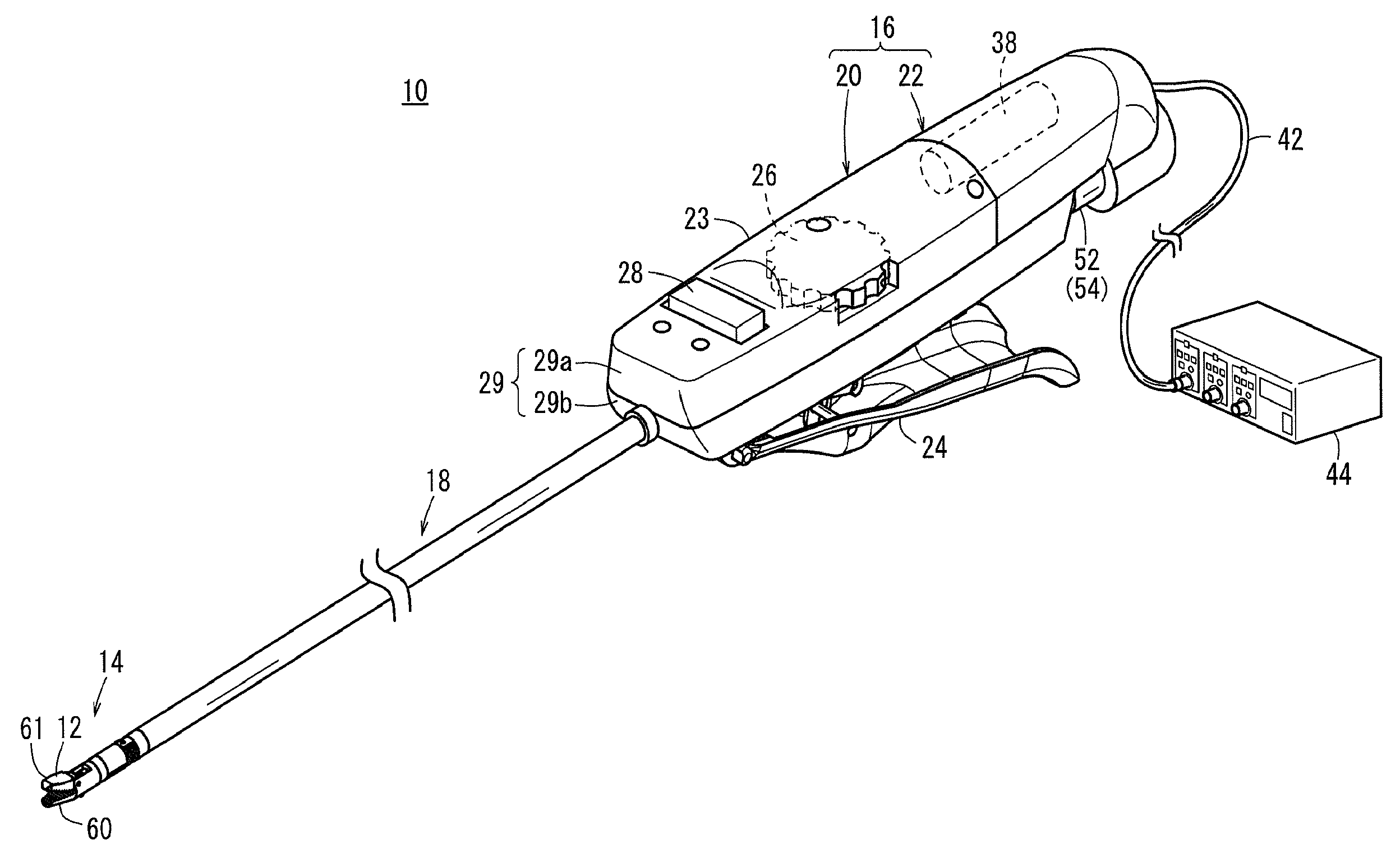
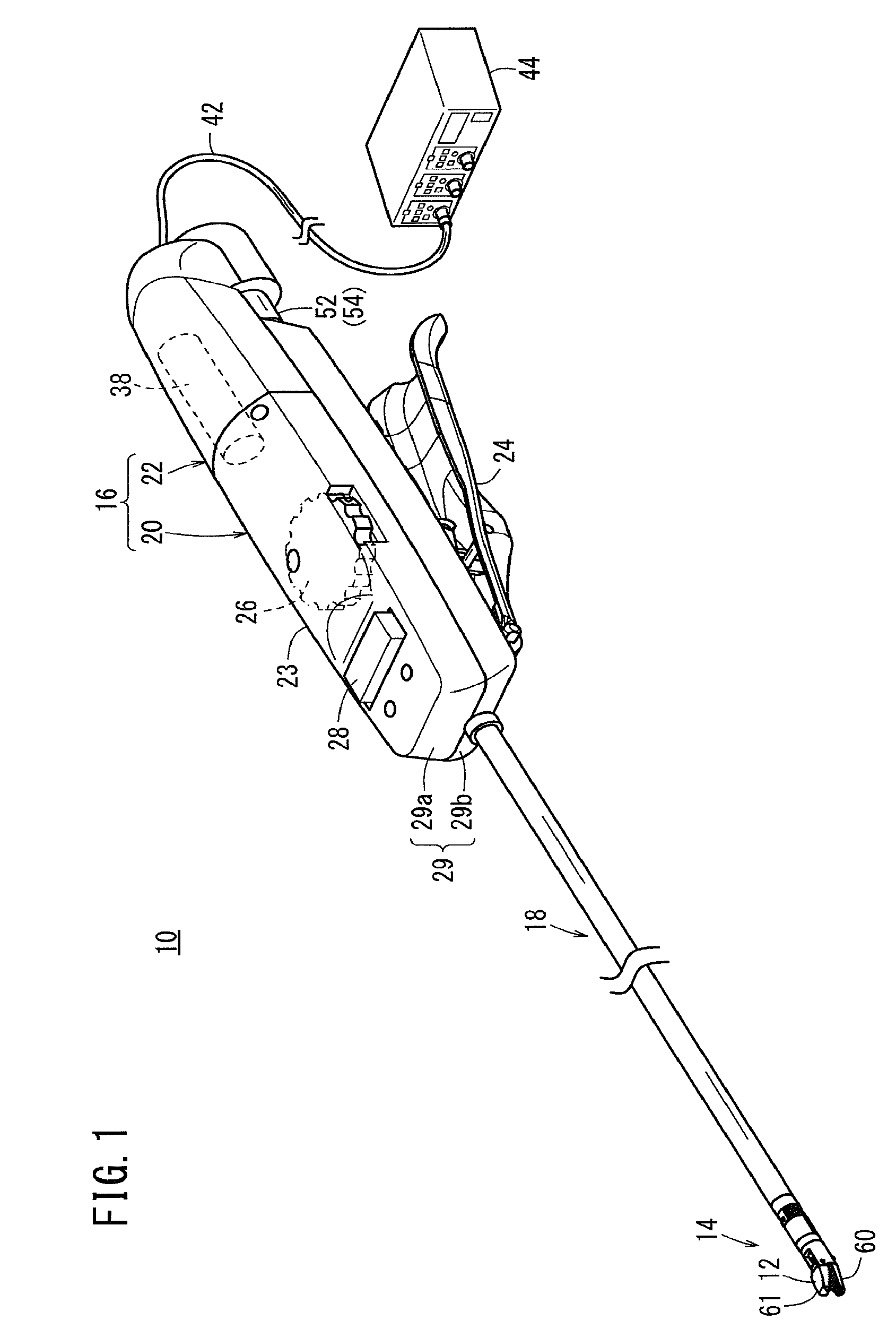
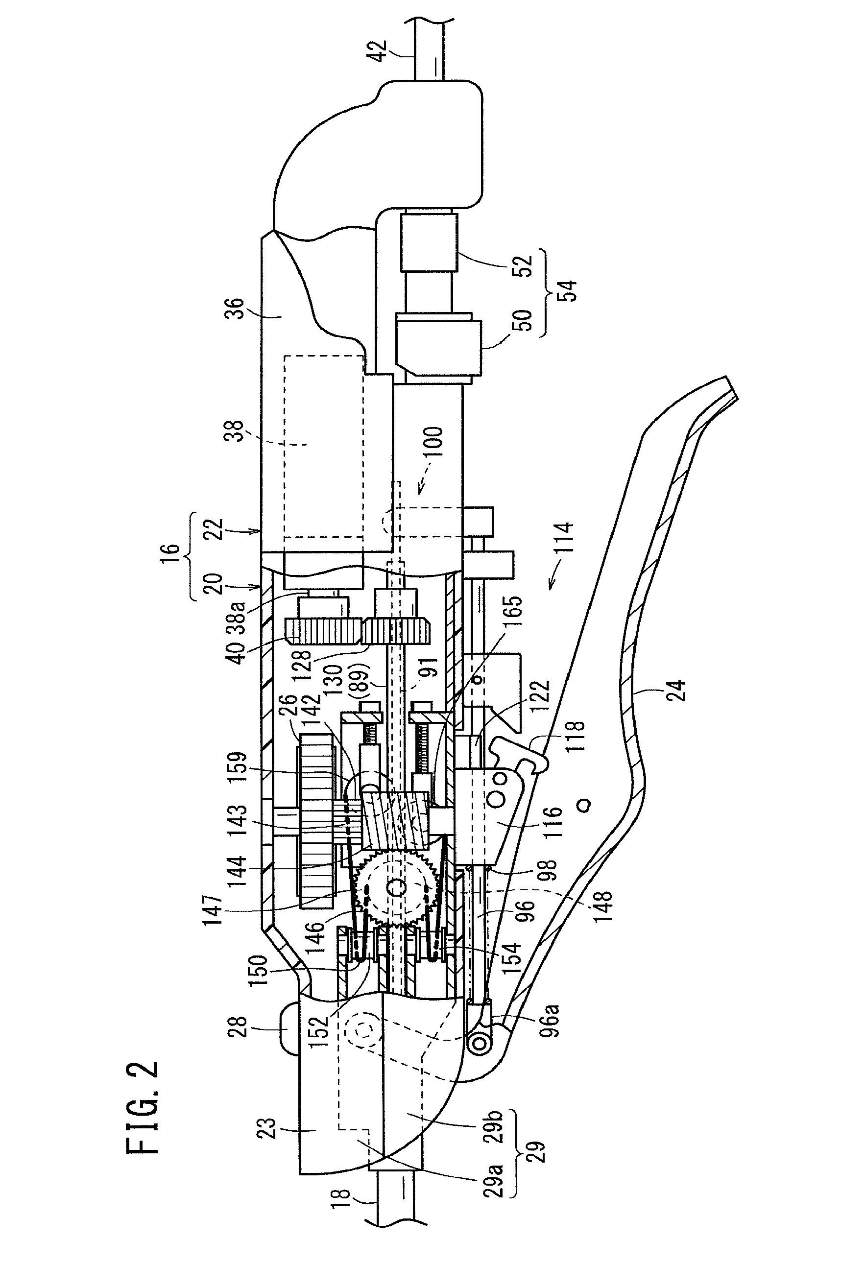
[0027]FIG. 1 is a partially-omitted, perspective view of a medical manipulator 10 according to a first embodiment of the present invention. The medical manipulator 10 is a medical implement that grasps a needle, a suture or a part of the living body or touches the living body using the end effector 12 provided at a distal end thereof, and carries out a predetermined treatment. Corresponding to the type of end effector 12 provided at the distal end, the medical manipulator 10 can be configured to have a grasping forceps, a needle driver, a monopolar electric scalpel, a bipolar electric scalpel, or the like.

[0028]Below, initially, the structure of a medical manipulator 10 in which a needle driver is used as one embodiment will be described in outline, followed by a detailed description of the structure of respective parts thereof.

[0029]The medical manipulator 10 is equipped with a distal end working unit 14 including an end effector 12, a handle 16 that drives the end effector 12, and...

second embodiment

[0086]FIG. 7 is a perspective view with partial omission of a medical manipulator 200 according to a second embodiment of the present invention. The medical manipulator 200 is used in an endoscopic surgical procedure, and is constructed so as to carry out a predetermined process (e.g., cauterization by application of heat) by applying electrical energy to a biological tissue that serves as a surgical target X to be treated. As a biological tissue that serves as the surgical target X, for example, tumors (lesions), muscles, blood vessels, or nerves, etc., may be cited as examples thereof. More specifically, the end effector 212 of the medical manipulator 200 is constituted as an end effector 212 (electric scalpel) that applies electrical energy to the biological tissue by gripping the biological tissue.

[0087]As shown in FIG. 7, the medical manipulator 200 comprises a distal end working unit 214 having an end effector 212 for carrying out a surgical procedure on a biological tissue, a...


PUM


Abstract

This medical manipulator is provided with a distal-end moving section including an end effector. The distal-end moving section includes a rotating sleeve (a distal-end rotator) which is able to rotate integrally with the end effector about a roll axis and has a hollow cylindrical portion, and a distal-end fulcrum block (rotary support cylinder) which is provided so as to be able to change orientation in relation to the axial direction of a shaft and rotatably supports the rotating sleeve at an inner peripheral section. A part of an opening / closing driving transmission section (actuating means) for transmitting an opening / closing driving force to the end effector is disposed inside of the distal-end moving section.

Description

FIELD OF THE INVENTION[0001]The present invention relates to a medical manipulator that is used when a surgical operation, and in particular an endoscopic surgical operation, is carried out, and in which a distal end working unit thereof having an end effector can be subjected to a rolling operation within an unlimited range of rotation.BACKGROUND OF THE INVENTION[0002]In an endoscopic surgical operation (also referred to as “laparoscopic surgery”), a plurality of holes are punctured in the abdomen and such of a patient, trocars (cylindrical instruments) are inserted through the holes, and a laparoscope (camera) and a plurality of forceps are inserted into the body cavity via each of the trocars. Grippers, scissors, and blades of an electric scalpel or the like for gripping biological tissue are mounted to the tip of the forceps as an end effector.[0003]If the laparoscope and the forceps are inserted into the body cavity, an operator operates the forceps while viewing a state of the...

Claims


Application Information

Patent Timeline
Patent Type & Authority Applications(United States)
IPC IPC(8): A61B17/29
CPCA61B2017/2947A61B17/29A61B17/2909A61B18/1445A61B19/22A61B2017/003A61B2017/00314A61B2017/00398A61B2017/00477A61B2017/2927A61B2017/2929A61B2017/2936A61B2017/2939A61B2017/2946A61B2019/2238A61B34/70A61B2034/306
Inventor SUZUKI, TSUNEYOSHIMUGISHIMA, HIROFUMI
Owner KARL STORZ GMBH & CO KG
Why Eureka
Try Eureka