Guiding system for a sliding door

a sliding door and guiding system technology, applied in the direction of door/window fittings, multi-purpose tools, construction, etc., can solve the problems of unsatisfactory noise, unsatisfactory guiding system characteristics, and inability to provide taut system characteristics

Active Publication Date: 2010-04-27
EDSCHA ENG GMBH
View PDF24 Cites 26 Cited by
  • Summary
  • Abstract
  • Description
  • Claims
  • Application Information

AI Technical Summary

Benefits of technology

[0010]It is the object of the invention to further develop the guiding system for a sliding door described in the introduction such that it is designed to be free of play, make as little noise as possible and have a taut system characteristic.

Problems solved by technology

Guiding systems of this type have the disadvantage that the rolling elements in the guide rails have play and are thus not guided accurately, the operation rather causing undesired noise and not providing a taut system characteristic.
It is disadvantageous that the arrangement is susceptible to noisy operation, the rollers not being guided in an entirely accurate and taut manner.
It is also disadvantageous that the rollers which are subject to wear over time lose contact with the runner rails and must then be adjusted by hand, which is complex, in order be able to lessen the noise of operation.
The arrangement in particular does not ensure that all of the rollers are in contact with an upper cover (upper rail) or a lower termination (lower rail) at all times. It is disadvantageous that the rollers have play which cannot be suppressed, so that operation of the sliding door is noisy.
It is disadvantageous that the compression spring is fixedly connected to the door by means of the bearing block, and hence in particular cannot move with the two rollers along the runner rail.
It is also disadvantageous that the overall construction is complex and is visually difficult to conceal.
It is disadvantageous that the carriage in the runner rail has play so that it is not guided in a secure and taut manner.
It is disadvantageous that the rolling elements have play which cannot be eliminated and which directly prevents a taut guidance of the sliding door.
It is also disadvantageous that the arrangement is of very complex design.

Method used


Image

  • Guiding system for a sliding door
  • Guiding system for a sliding door
  • Guiding system for a sliding door

Examples


Embodiment Construction

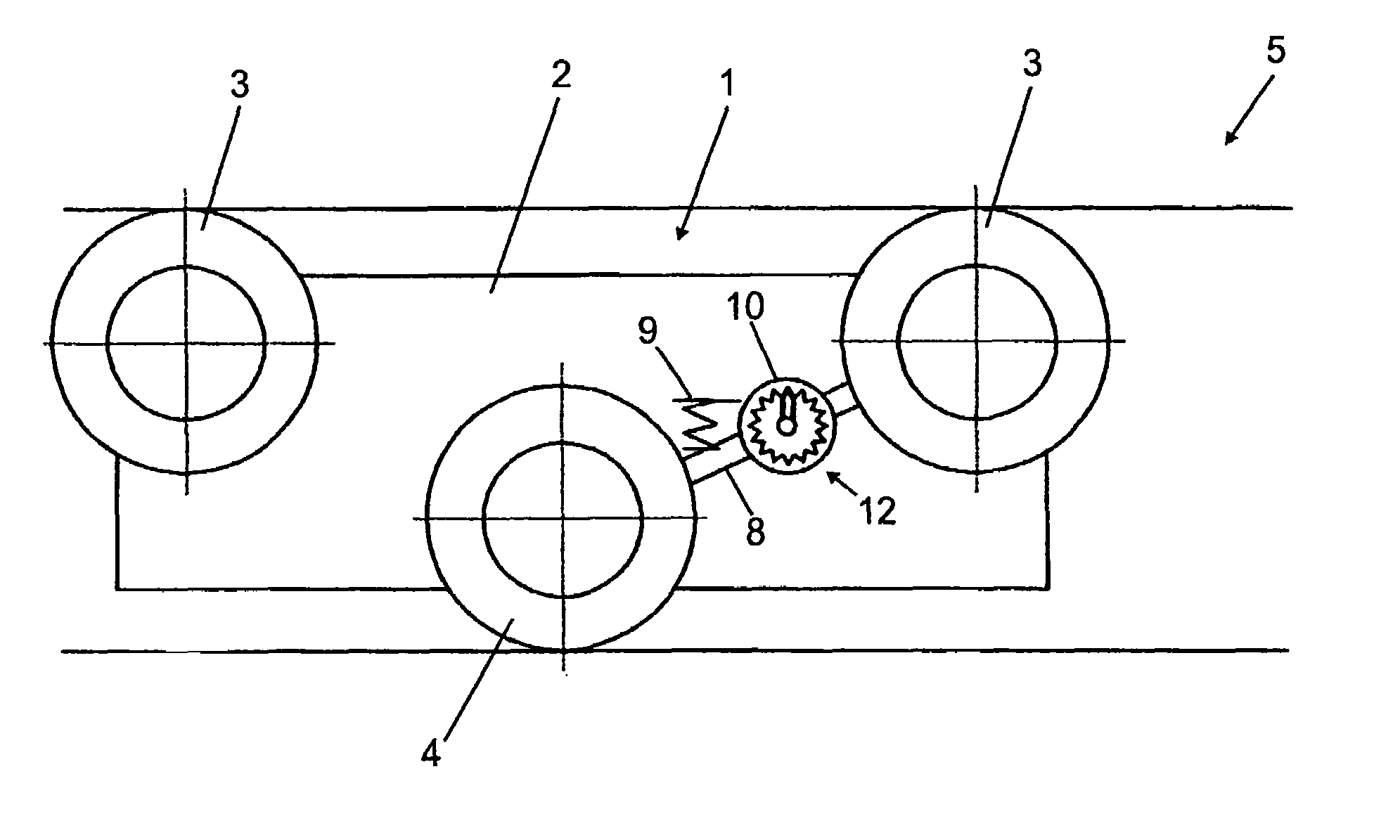
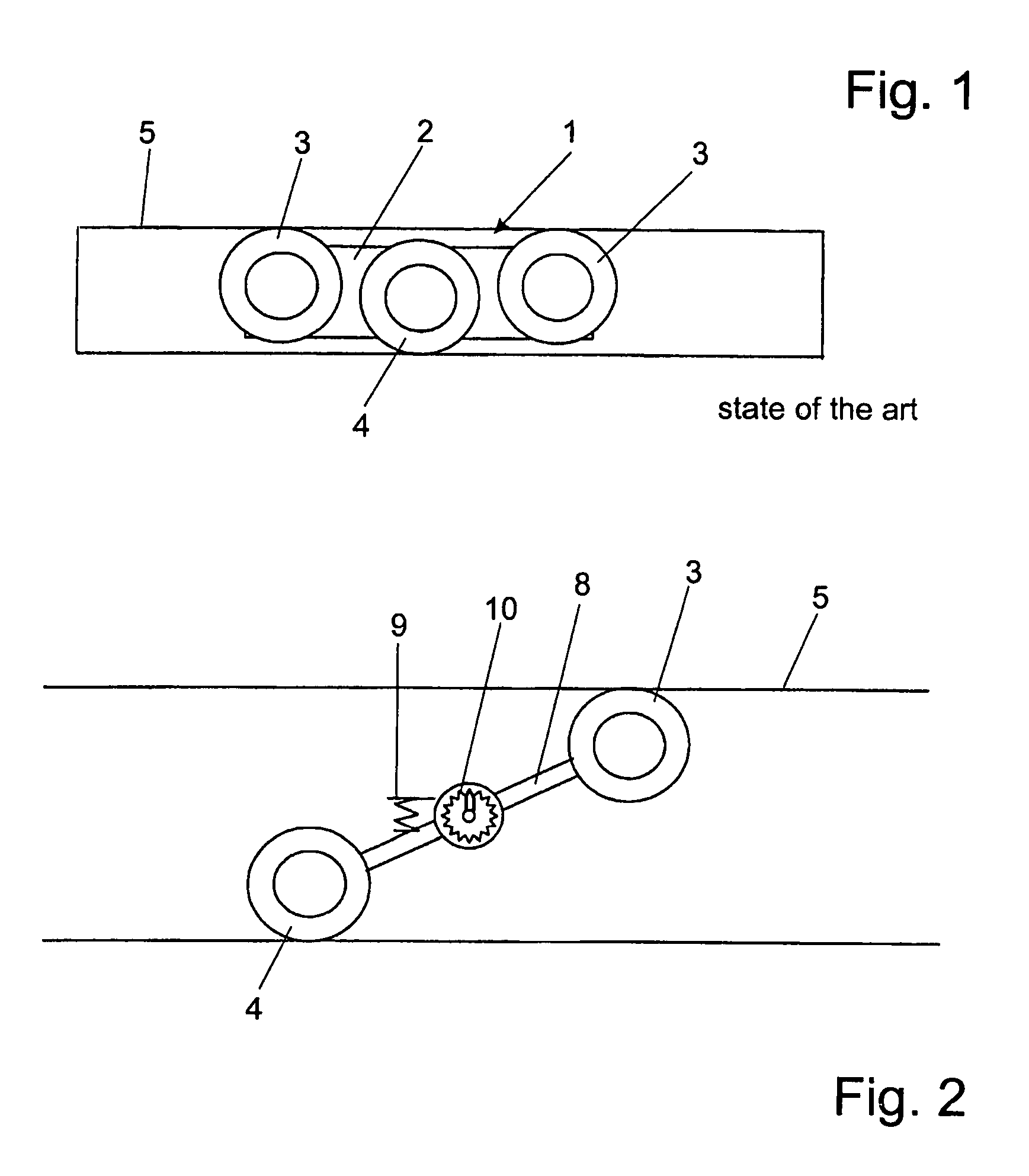
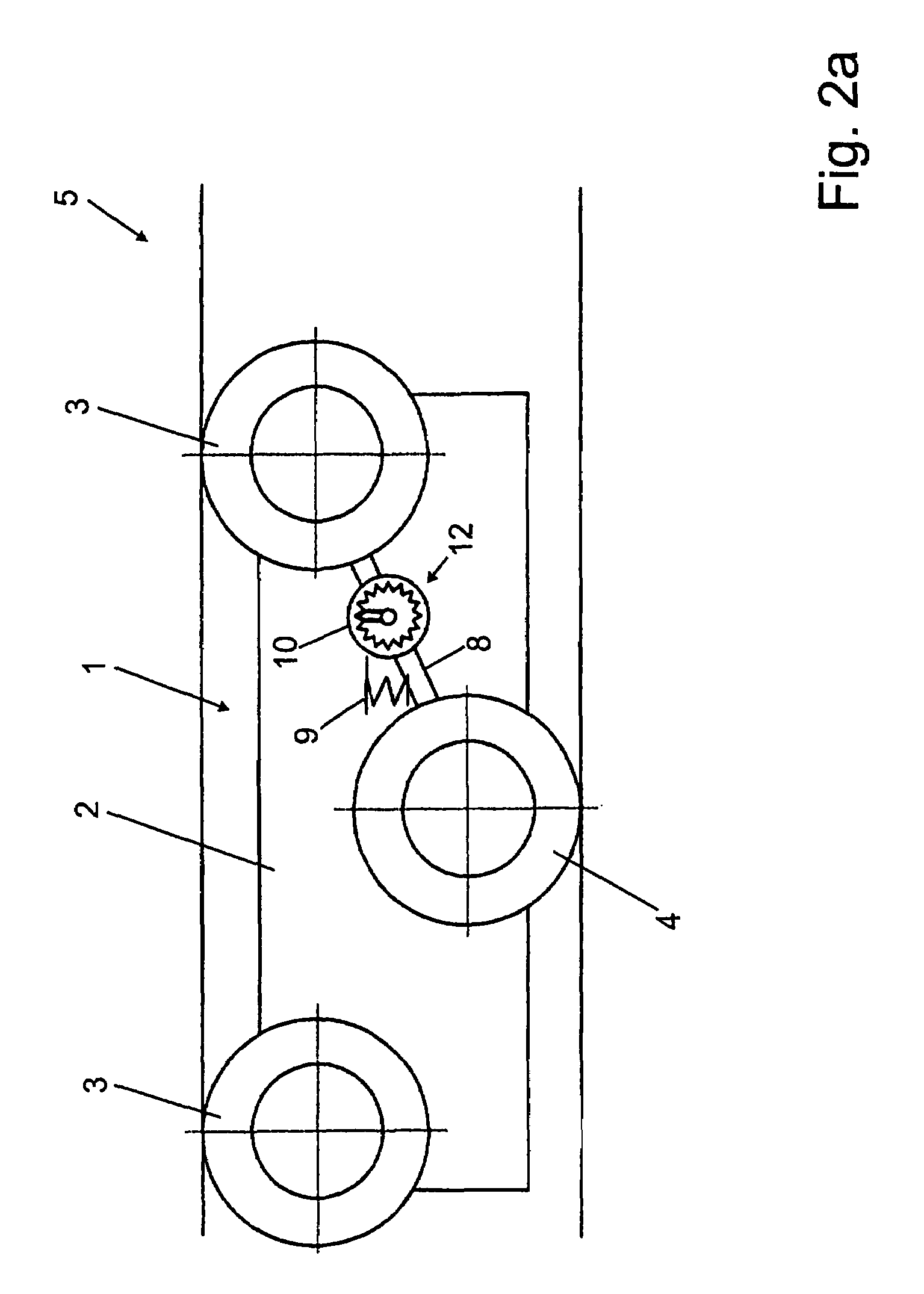
[0027]FIG. 1 schematically illustrates how a rolling element 1 designed as a carriage, with three rollers offset in relation to one another, of which two upper rollers 3 bear against the upper cover 6 and a lower roller 4 bears against the lower termination 7 of the runner rail 5, is guided. The three rollers 3, 4 are mounted so as to be rotatable about horizontal axes on a rolling element housing 2. It can be seen that this form of offset arrangement of upper rollers 3 and lower roller 4 allows a stable three-point support. The stiffness in the longitudinal direction necessary for a taut system characteristic is also favourably influenced by the aligned arrangement of the upper roller 3. Such guiding systems are known from the prior art but require a constant readjustment of the setting of the rollers 3, 4 in order to ensure a secure operation of the rolling element 1.

[0028]In FIG. 2, only one of the upper rollers 3 and the lower roller 4 are illustrated, and these are connected to...


PUM


Abstract

A guiding system for a sliding door, especially a motor vehicle, comprising a sliding rail (5) with an upper cover (6) and a lower edge (7) arranged opposite the upper cover (6), and a roller element (101) which is guided in the sliding rail (5) and comprises a roller element housing (102) is presented. Three rollers (103, 104) are rotatably fixed to the roller element housing (102), two rollers (103) extending along the upper cover (6) of the sliding rail (5) and the third roller (104) extending along the lower edge (7). The invention creates one such guiding system in such a way that there is no play, it operates quietly, and has a taut system characteristic. To this end, a spring element (109) is fixed to the roller element housing (102), said spring element pressing on of the first two roller (103) and the third roller (104) against the sliding rail (5).

Description

[0001]The invention relates to a guiding system for a sliding door, in particular for a motor vehicle comprising a runner rail with an upper cover and a lower termination arranged opposite the upper cover, a rolling element, with a rolling element housing being guided in the runner rail, three rollers being rotatably fastened to the rolling element housing with each of the three rollers being rotatable about a horizontal axis, a first roller and a second roller of the three rollers running along the runner rail against the upper cover and the third roller running along the runner rail against the lower termination.BACKGROUND[0002]Guiding systems of the as-cited type for sliding doors for vehicles and motor vehicles are known from the prior art. Guiding systems of this type have the disadvantage that the rolling elements in the guide rails have play and are thus not guided accurately, the operation rather causing undesired noise and not providing a taut system characteristic.[0003]Gu...

Claims


Application Information

Patent Timeline
Patent Type & Authority Patents(United States)
IPC IPC(8): E05D13/00E05D15/06E05D15/10E05F7/04
CPCE05D15/0621E05D15/101E05F7/04E05Y2201/614E05Y2201/64Y10T16/3837E05Y2900/531E05Y2600/322E05Y2201/612Y10T16/3825Y10T16/367E05Y2201/688E05Y2800/422E05D15/0652E05D2015/1057E05D15/1047
Inventor GOEBEL, MARKUSDUNING, RALF
Owner EDSCHA ENG GMBH
Why Eureka
Try Eureka