Motor Vehicle Driving Train and Process For Controlling an Automated Engine Clutch

Inactive Publication Date: 2008-08-14
ZF FRIEDRICHSHAFEN AG
View PDF8 Cites 4 Cited by
  • Summary
  • Abstract
  • Description
  • Claims
  • Application Information

AI Technical Summary

Benefits of technology

[0016]All in all, compared to the known clutch constructions, this results in improved controllability, enables a simple and low cost control device to control the clutch actuator and an inexpensive and space-saving mounting of the motor clutch. Thus the spring-supported pressing device and the clutch components stressed by it can be constructed relatively simply and economically because of the lower stress.
[0017]Since the basi

Problems solved by technology

It thus primarily involves a relatively complex directional control of an automatic friction clutch.
The disadvantage of this type of clutch construction, however, is the high complexity of component parts, in particular for the pressing device and the disengaging device, as well as the high, technical complexity of the clutch control which is especially required due to the non-proportional spring characteristic of the membrane spring.
In addition, there is also the fact, that to adjust a certain coupling torque, starting from the condition of rest, the actuator first must bridge an empty run and then remove the excess pressure, which results in a definite delay and a poor response of the clutch control.
A serious disadvanta

Method used


Image

  • Motor Vehicle Driving Train and Process For Controlling an Automated Engine Clutch
  • Motor Vehicle Driving Train and Process For Controlling an Automated Engine Clutch
  • Motor Vehicle Driving Train and Process For Controlling an Automated Engine Clutch

Examples


Example

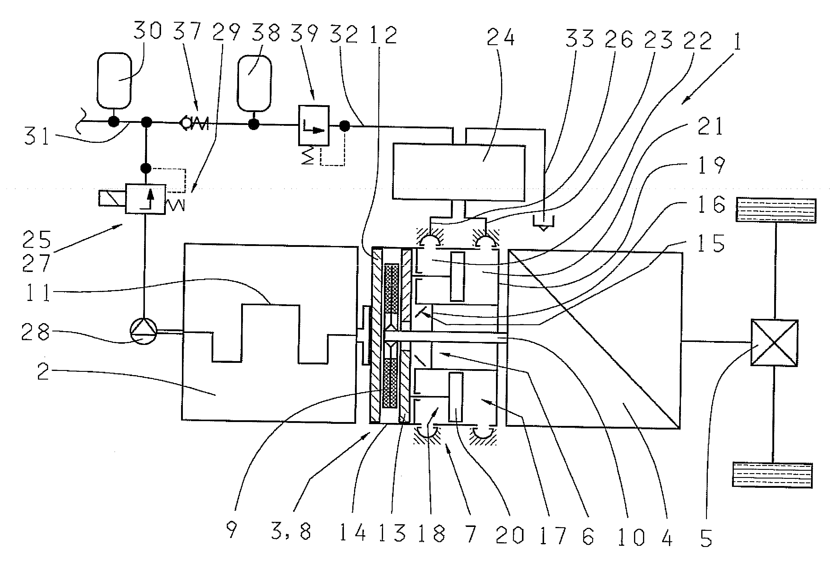
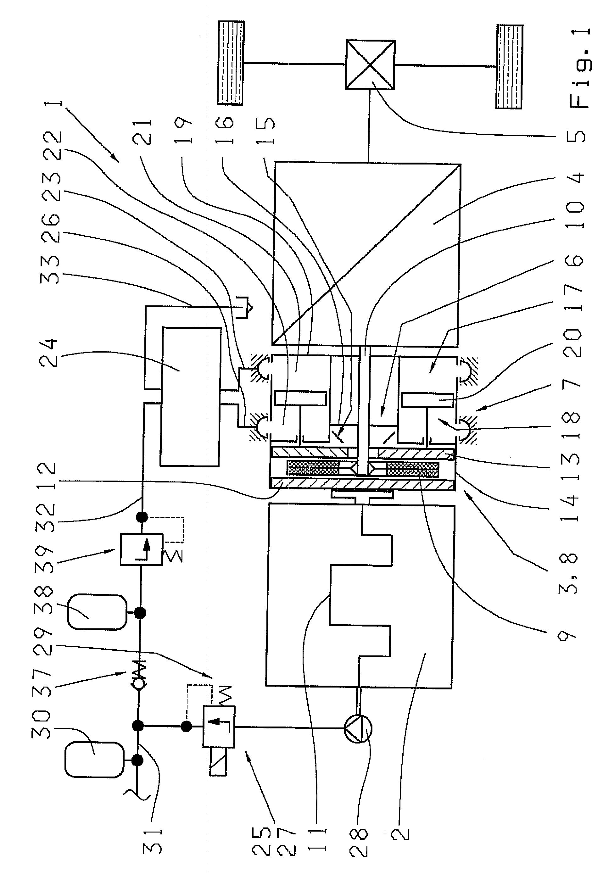
[0040]According to FIG. 1 a power train 1 of a motor vehicle includes a drive motor 2 constructed as a combustion engine, a transmission 4 with variable, i.e. shiftable in stages or continuously varying, transmission ratios connected to an axle drive 5, and with an automatic motor clutch 3, constructed as a passively lockable friction clutch by means of a spring-loaded pressing device 6 and whose transferable torque (coupling torque) is adjusted using a clutch actuator 7, located in the power flow between the drive motor 2 and the transmission 4.

[0041]The motor clutch 3 is constructed primarily a single-plate dry clutch B. Thus a supported, axially shiftable clutch plate 9 is placed in a known manner on the input shaft 10 of the transmission 4, between a flywheel 12 that is rigidly connected with a crankshaft 11 of the drive motor and a pressure plate 13 on the transmission side. The pressure plate 13 rotationally fixed but axially shiftable in a clutch cover 14 which is rigidly con...


PUM


Abstract

A power train of a motor vehicle with a drive motor (2), a transmission (4) with variable transmission ratios connected to an axle drive (5), and an automatic motor clutch. The automatic motor clutch is a passively lockable friction clutch actuated by a spring-loaded pressing device (6) and whose transferable rotational toque (coupling torquet) is adjusted using a clutch actuator (7), and is located in the flow of power between the drive motor (2) and the transmission (4). Improved controllability and a more rapid response of the motor clutch (3) is achieved by the spring-supported pressing device (6) to produce a basic coupling torque below the maximum rotational torque of the drive motor (2) and, a second pressing device (17) regulates a higher coupling torque by way of an effective connection with the clutch actuator (7).
The invention involves a power train of a motor vehicle with a drive motor (2) constructed as a combustion engine, a transmission (4) with variable transmission ratios connected to an axle drive (5), and with an automatic motor clutch, which is constructed as a passively lockable friction clutch by means of a spring-loaded pressing device (6) and whose transferable rotational moment (coupling moment) is adjusted using a clutch actuator (7), located in the power flow between the drive motor (2) and the transmission (4). To achieve an improved controllability and a more rapid response of the motor clutch (3) the spring-supported pressing device (6) is designed to produce a basic coupling moment lying below the maximum rotational moment of the drive motor (2) and to regulate a higher coupling moment a second pressing device (17) is provided in an effective connection with the clutch actuator (7).

Description

[0001]This application is a national stage completion of PCT / EP2006 / 003508 filed Apr. 18, 2006 which claims priority from German Application Serial No. 10 2005 021 416.9 filed May 10, 2005.FIELD OF THE INVENTION[0002]The invention involves a power train of a motor vehicle with a drive motor constructed as a combustion engine, a transmission with variable transmission ratios connected to an axle drive, and with an automatic motor clutch, which is constructed as a friction clutch passively lockable by way of a spring-loaded pressing device and whose torque transfer (coupling moment) is adjusted using a clutch actuator, located in the power flow between the drive motor and the transmission.[0003]The invention also involves a procedure to control an automatic motor clutch placed in the power train of a motor vehicle in the power flow between a drive motor constructed as a combustion engine and a transmission with variable transmission ratios connected to an axle drive, with the clutch c...

Claims


Application Information

Patent Timeline
IPC IPC(8): F16D48/06
CPCF16D48/02F16D2500/1026F16D2500/1028Y10T477/6425F16D2500/1045F16D2500/3024F16D2500/501F16D2500/10412
Inventor PETZOLD, RAINERSTEINBORN, MARIO
Owner ZF FRIEDRICHSHAFEN AG
Why Eureka
Try Eureka