Clutch driven stent delivery system

a stent and stent technology, applied in the field of stent delivery systems, can solve the problems of ineffective devices and methods of achieving proper angular orientation, ineffective placement and positioning of stents, and previously inadequate treatment of sites by stents

Inactive Publication Date: 2005-02-17
BOSTON SCI SCIMED INC
View PDF101 Cites 179 Cited by
  • Summary
  • Abstract
  • Description
  • Claims
  • Application Information

AI Technical Summary

Benefits of technology

[0024] In at least one embodiment the slit in the open configuration allows for retraction of the sheath along a first

Problems solved by technology

Although efforts have been made to use a stent at bifurcations, these sites have previously been inadequately treated by a stent.
However, problems are still encountered in orienting the stent relative to the side branch at the bifurcation of the main and branch passages.
These devices and methods of achieving proper angular orientation have not been shown to be effective in properly placing and positioning the stent.
As wil

Method used


Image

  • Clutch driven stent delivery system
  • Clutch driven stent delivery system
  • Clutch driven stent delivery system

Examples


Embodiment Construction

[0080] While this invention may be embodied in many different forms, there are described in detail herein specific preferred embodiments of the invention. This description is an exemplification of the principles of the invention and is not intended to limit the invention to the particular embodiments illustrated.

[0081] For the purposes of this disclosure, like reference numerals in the figures shall refer to like features unless otherwise indicated.

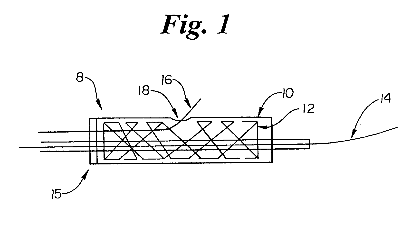
[0082] In FIG. 1 a side view of an embodiment of a distal member 8 of the invention is shown. Here the sheath 10 covers a stent 12 having a first guidewire 14 and a second guidewire 16 passing through it. Such a stent 12 can be used in a vessel bifurcation. In some embodiments the distal member 8 is advanced along two guide wires 14 and 16. The first guidewire 14 is positioned in the primary passage or branch vessel and the second guidewire 16 diverges from the first guidewire 14 upon passage into the secondary branch in the region of t...


PUM


Abstract

A catheter assembly has an engaged state and an unengaged state comprising a proximal member having a longitudinal axis and a distal member having a longitudinal axis. A distal end of the proximal member is removably engageable to the distal member. The distal member has a first distal portion and a second distal portion, and the first distal portion is retractable from the second distal portion. In the engaged state the distal member is substantially freely rotatable about its longitudinal axis and in relation to the proximal member. In the engaged state the proximal member is constructed and arranged to be moved in a direction along the longitudinal axis such that proximal movement of the proximal member retracts at least the first distal portion of the distal member from at least the second distal portion.

Description

CROSS-REFERENCE TO RELATED APPLICATIONS [0001] Not Applicable STATEMENT REGARDING FEDERALLY SPONSORED RESEARCH [0002] Not Applicable BACKGROUND OF THE INVENTION [0003] 1. Field of the Invention [0004] At least one embodiment of the present invention is directed to the field stent delivery systems used to treat stenoses, and more particularly to stenoses at a bifurcation of a passage. [0005] 2. Description of the Related Art [0006] Stent systems are widely used in the treatment of stenoses. Intravascular stents are used in coronary, renal, and carotid arteries, for example, to maintain an open passage through the artery. In patients whose coronary heart disease consists of focal lesions, stents have proven effective. For example, where only a single coronary artery is clogged or where there are short blockages in more than a single artery, stents have been used with a great amount of success. An intravascular stent may be positioned in a clogged artery by a catheter assembly and is o...

Claims


Application Information

Patent Timeline
IPC IPC(8): A61F2/84
CPCA61F2/95A61M2025/1015A61F2002/9665A61F2/97
Inventor EIDENSCHINK, TRACEE
Owner BOSTON SCI SCIMED INC
Why Eureka
Try Eureka