Endoscopic stapler having camera

a technology of endoscopic staplers and cameras, applied in the field of staplers, can solve the problems of complex arrangement of cams, etc., requiring complex manufacturing and assembly methods, and varying degrees of complexity

Active Publication Date: 2011-06-14
MEDIGUS LTD
View PDF21 Cites 1155 Cited by
  • Summary
  • Abstract
  • Description
  • Claims
  • Application Information

AI Technical Summary

Problems solved by technology

The mechanical arrangement of the cams, etc. is of varying degrees of complexity, but in all cases is not simple and requires complex manufacturing and assembly methods and unnecessary expense all of which could be reduced if a simpler stapler firing method could be devised.

Method used


Image

  • Endoscopic stapler having camera
  • Endoscopic stapler having camera
  • Endoscopic stapler having camera

Examples


Embodiment Construction

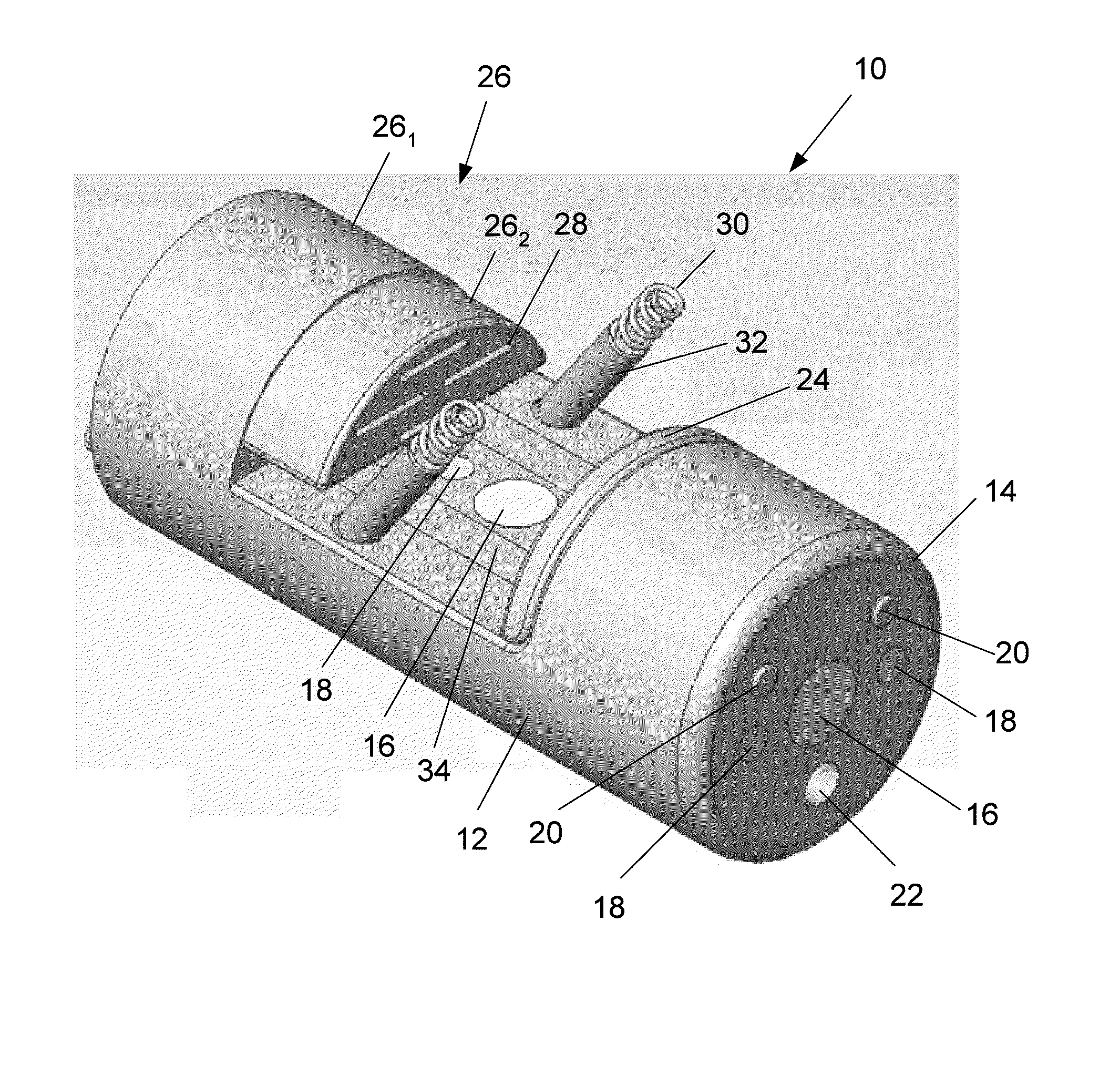
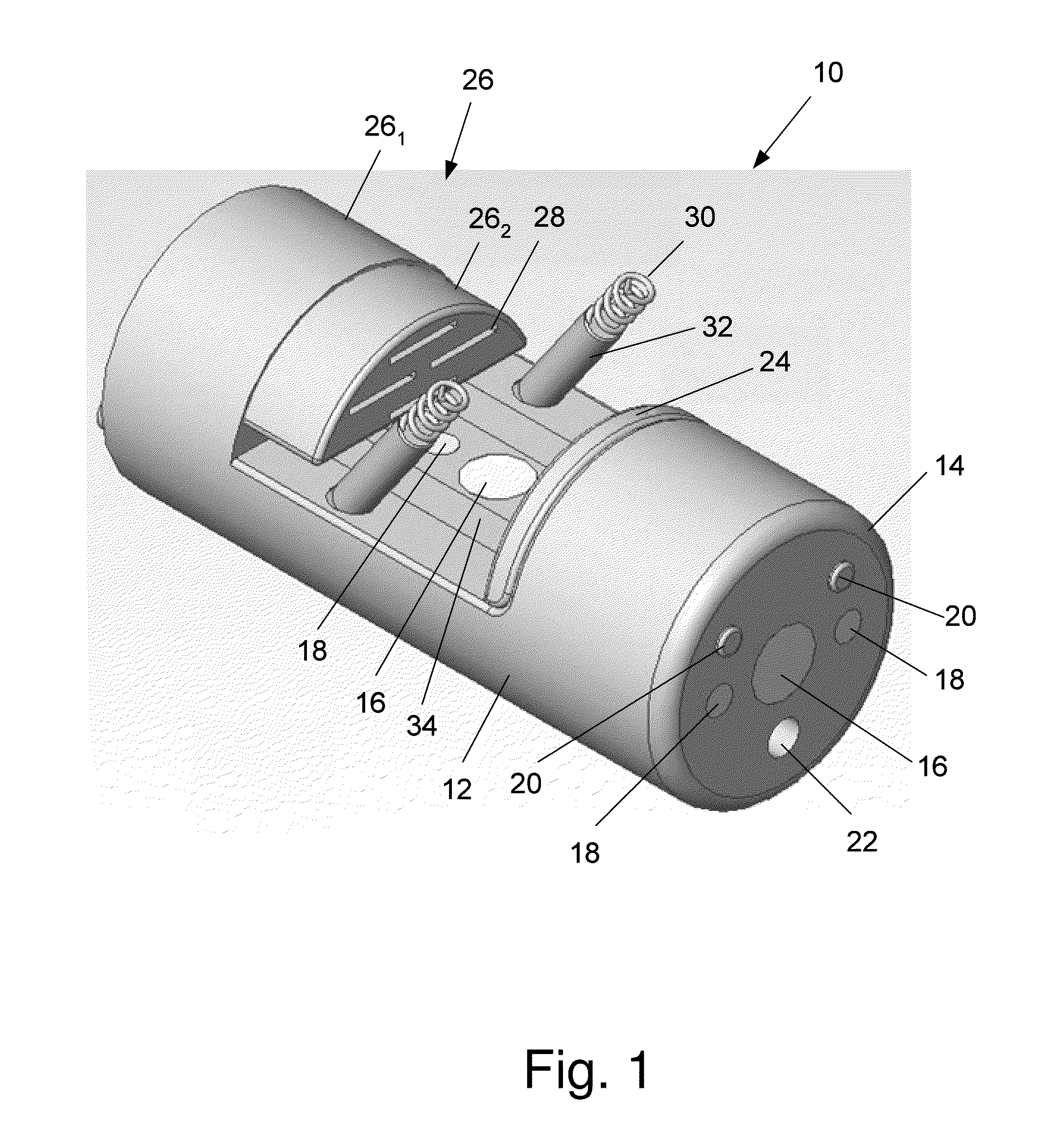
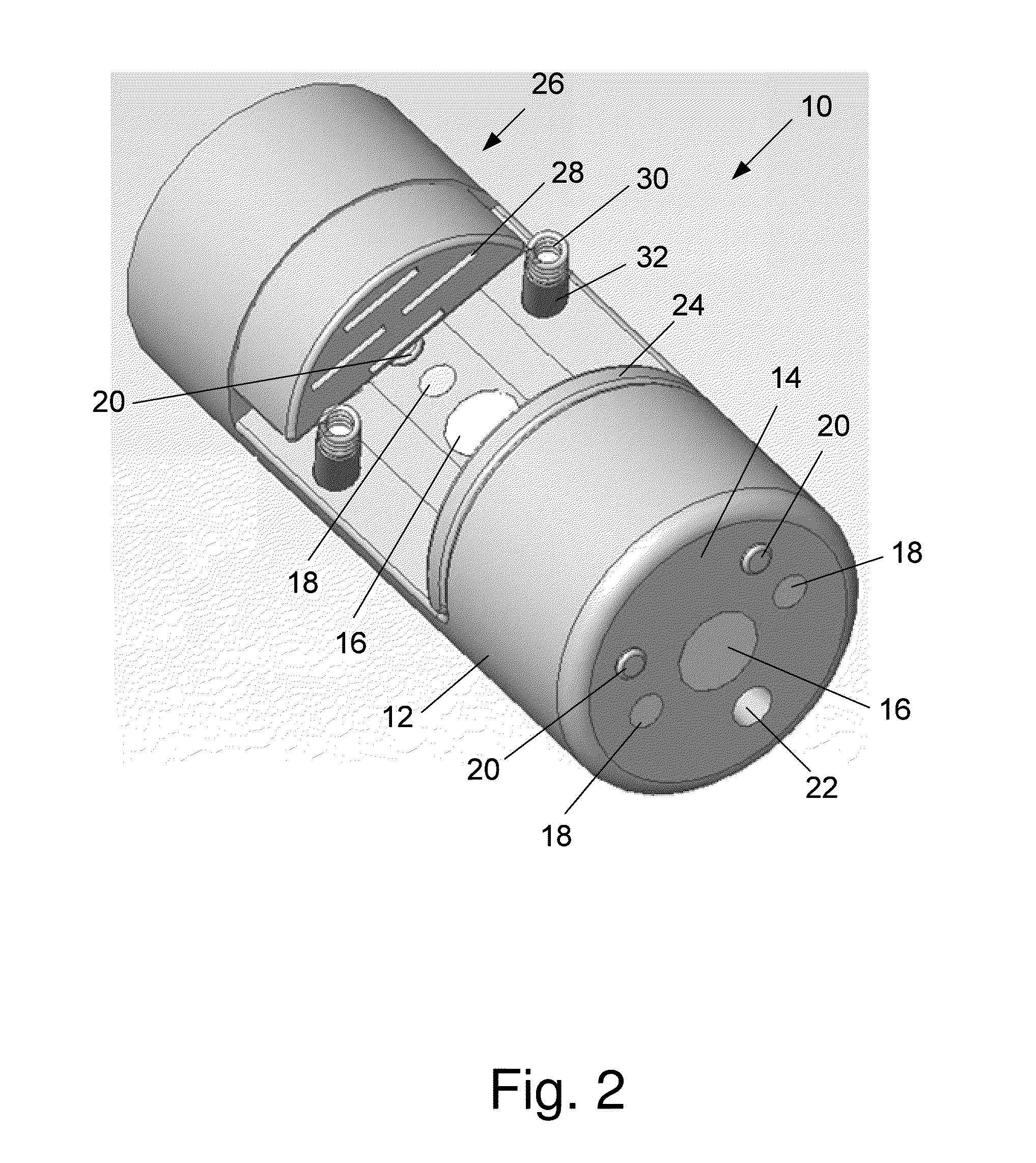
[0042]The stapler device of the invention comprises an anvil and staple cartridge located in the distal tip of an endoscopic device which can have either a rigid (i.e. laparoscope), semi-rigid, or flexible insertion section. According to a preferred embodiment of the invention the insertion tube of the endoscopic device comprises a proximal flexible section followed by an articulation section. The stapler of the invention has two embodiments, a side fastening embodiment and a front fastening embodiment. The endoscopic device that comprises the stapler can be used to perform many different stapling tasks, e.g. closure of a hole in the wall of an internal organ. The endoscopic device comprising the stapler of the invention can be either totally or partially sterilized after each use or, in some embodiments disposed after a single procedure has been performed.

[0043]FIG. 1 to FIG. 8 and FIG. 10 show different views of the side fastening embodiment of the invention in order to assist in ...


PUM

PropertyMeasurementUnit
sizesaaaaaaaaaa
sizesaaaaaaaaaa
sizesaaaaaaaaaa

Abstract

The invention is a stapler device comprising an anvil and staple cartridge located in the distal tip of an endoscopic device. The staple cartridge is comprised of a fixed proximal portion and a moveable distal portion, which slides into said fixed portion. Means are provided for moving the anvil back and forth, such that the anvil pushes against the distal face of the staple cartridge thereby pushing the moveable portion of the staple cartridge into the fixed portion and causing the staples to be ejected from said staple cartridge passively without said staples moving. The stapler of the invention has two embodiments, a side fastening embodiment and a front fastening embodiment. The endoscopic device that comprises the stapler can be used to perform many different stapling tasks, e.g. closure of a hole in the wall of an internal organ.

Description

CLAIM OF PRIORITY[0001]This application claims priority as a 371 of international of PCT / IL2007 / 000659, filed on May 31, 2007; which claims priority to Israeli patent application number 176133, filed on Jun. 5, 2006.FIELD OF THE INVENTION[0002]The present invention is related to the field of staplers. Specifically the invention relates to the field of linear surgical staplers and endoscopic staplers.BACKGROUND OF THE INVENTION[0003]Linear surgical staplers are well known in the prior art. Typical examples of such devices are described in WO 00 / 53102, U.S. Pat. No. 5,772,099, U.S. Pat. No. 5,676,674, U.S. Pat. No. 5,389,098, and U.S. Pat. No. 6,872,214. All of these devices comprise a staple cartridge in which is stored one or more arrays of staples. The essentially U-shaped staples are stored with their legs aligned with and pointing in the direction of slots in the face of the cartridge. The staples actively forced to move through the slots when the firing mechanism is activated. T...

Claims


Application Information

Patent Timeline
Patent Type & Authority Patents(United States)
IPC IPC(8): A61B17/064
CPCA61B17/0057A61B17/072A61B2017/07214A61B2017/00349A61B2017/00668A61B2017/003
Inventor SONNENSCHEIN, ELAZARGOVRIN, AMIR
Owner MEDIGUS LTD
Why Eureka
Try Eureka