Power train for a motor vehicle

a technology for motor vehicles and power trains, applied in the direction of electric generator control, engine starters, gearing, etc., can solve the problems of increasing weight and cost, and achieve the effects of cost saving, long operating life of interactive connections, and easy handling

Inactive Publication Date: 2002-08-29
LUK LAMELLEN & KUPPLUNGSBAU BETEILIGUNGS KG
View PDF0 Cites 190 Cited by
  • Summary
  • Abstract
  • Description
  • Claims
  • Application Information

AI Technical Summary

Benefits of technology

0006] The present invention therefore has the objective of improving a power train of the kind described above by providing an interactive connection between the electro-mechanical energy converter and the combustion engine with a means of changing the trans

Problems solved by technology

The additional transducer and control means required with t

Method used


Image

  • Power train for a motor vehicle
  • Power train for a motor vehicle
  • Power train for a motor vehicle

Examples


Embodiment Construction

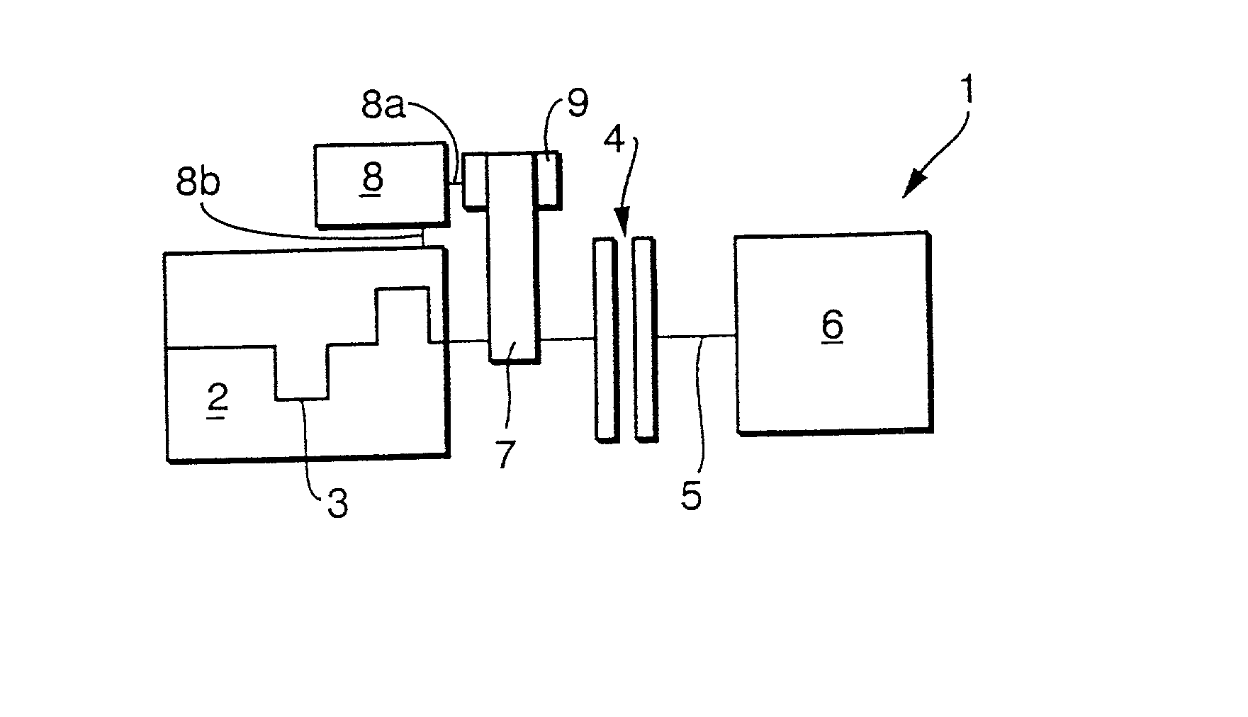
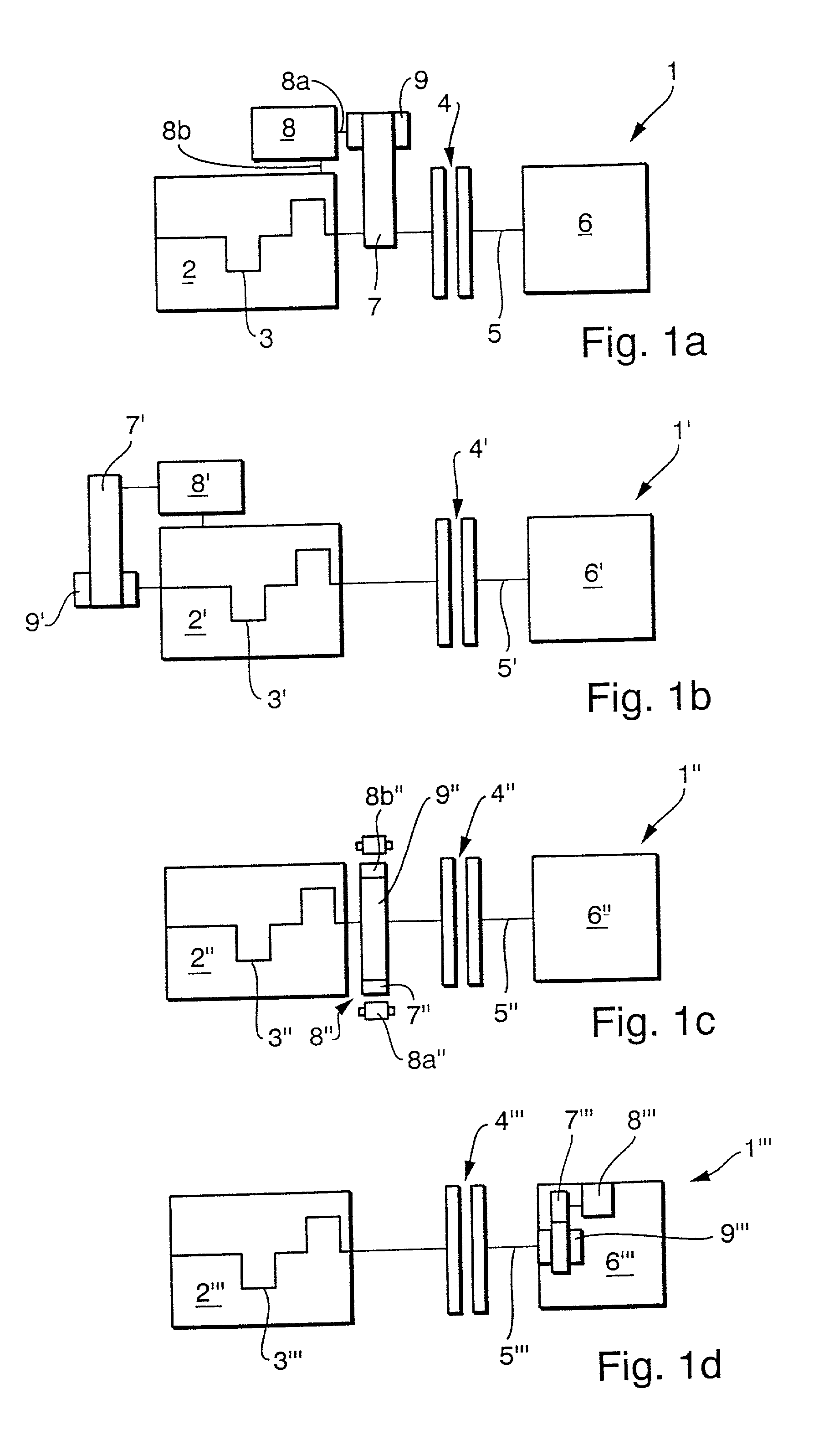
[0073] FIGS. 1a-d illustrate different possible arrangements of a power train 1, 1', 1", 1'" according to the invention with a drive source 2, 2', 2", 2'", e.g., a combustion engine, with a driving shaft or output shaft 3, 3', 3", 3'" that can be coupled by means of a clutch 4, 4', 4", 4'" to the input shaft 5, 5', 5", 5'" of a driven unit 6, 6', 6", 6'", e.g., a transmission such as a speed-changing transmission, an automatic transmission with multiple steps, or a continuously variable transmission (CVT). An electro-mechanical energy converter 8, 8', 8", 8'" is connected to the output shaft 3, 3', 3" in FIG. 1a-c, and to the input shaft 5'" in FIG. 1d through an interactive transfer connection 7, 7', 7", 7'" that transfers torque and shifts the torque-transfer ratio automatically dependent on the torque-flow direction by means of a rotary transfer device 9, 9', 9", 9'".

[0074] In the embodiment of FIG. 1a, the interactive connection 7 between the clutch 4 and the combustion engine 2...


PUM


Abstract

A power train for a motor vehicle includes a combustion engine, a clutch or other torque-coupling device, a transmission, and an electro-mechanical energy converter that is operable at least as a motor and as a generator. The electro-mechanical energy converter is coupled to the output shaft of the combustion engine through a torque transfer device with at least two rpm ratios that automatically set themselves according to whether the vehicle is operating in a start-up mode or in a driving mode.

Description

[0001] The invention relates to a motor vehicle power train including a drive source such as a combustion engine with a driving shaft, a driven unit with a driven shaft such as a transmission with a transmission input shaft, as well as at least one electro-mechanical energy converter interacting with the power train, and at least one clutch that is arranged in the torque flow path between the driving shaft and the driven shaft and serves to couple and uncouple the torque flow between the drive source and the driven unit.[0002] Arrangements of this kind are known from the German laid-open application DE-OS 32 30 121 as hybrid drives with an electric motor and a combustion engine, or from the German patent DE-PS 41 12 215 as combustion engines with a starter-generator.[0003] Depending on the specific layout, the electro-mechanical energy converter may be arranged either coaxially surrounding the rotational axis of the combustion engine--as known for example from the German laid-open a...

Claims


Application Information

Patent Timeline
IPC IPC(8): B60W10/08B60K6/365B60K6/387B60K6/40B60K6/405B60K6/48B60K6/485B60K6/543B60L50/16B60W10/00B60W10/02B60W10/10F02N11/04F16D27/09F16H3/54F16H37/06F16H61/66
CPCB60K6/365B60K6/387B60K6/40B60K6/405B60K6/48B60K6/485B60K6/543B60W10/02B60W20/00F02N11/04F16H3/54F16H61/66Y02T10/6221Y02T10/6226Y10S903/91B60K2006/268Y02T10/62B60K6/445B60W20/10
Inventor MAN, LASZLOREIK, WOLFGANGMULLER, BRUNO
Owner LUK LAMELLEN & KUPPLUNGSBAU BETEILIGUNGS KG
Why Eureka
Try Eureka