
Methods for regulating the gear ratio of an automatic power-branched transmission, and automatic power-branched transmission

Inactive Publication Date: 2005-10-13
LUK LAMELLEN & KUPPLUNGSBAU BETEILIGUNGS KG
View PDF16 Cites 195 Cited by
  • Summary
  • Abstract
  • Description
  • Claims
  • Application Information

AI Technical Summary

Benefits of technology

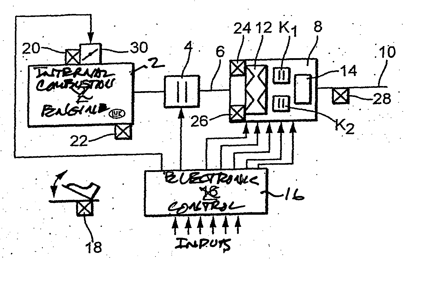
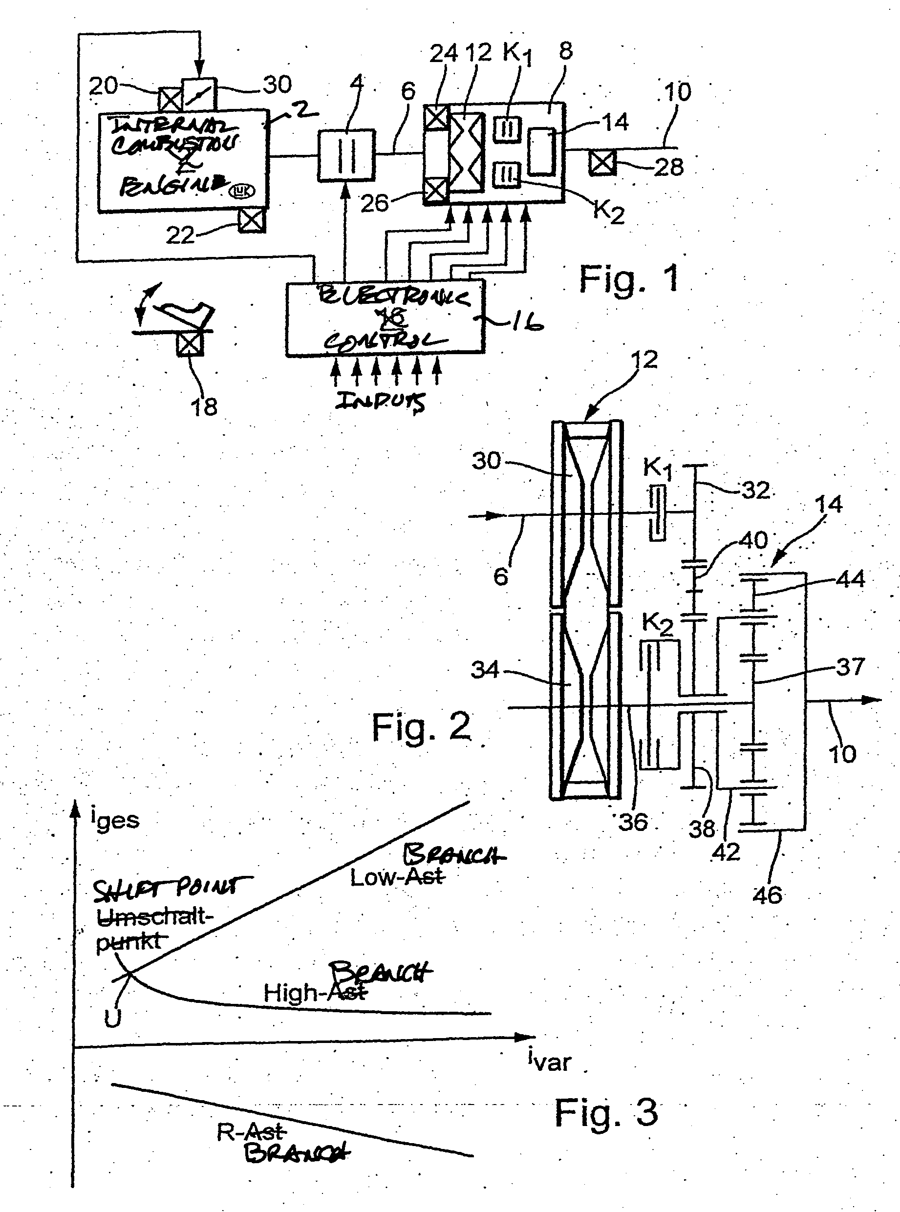
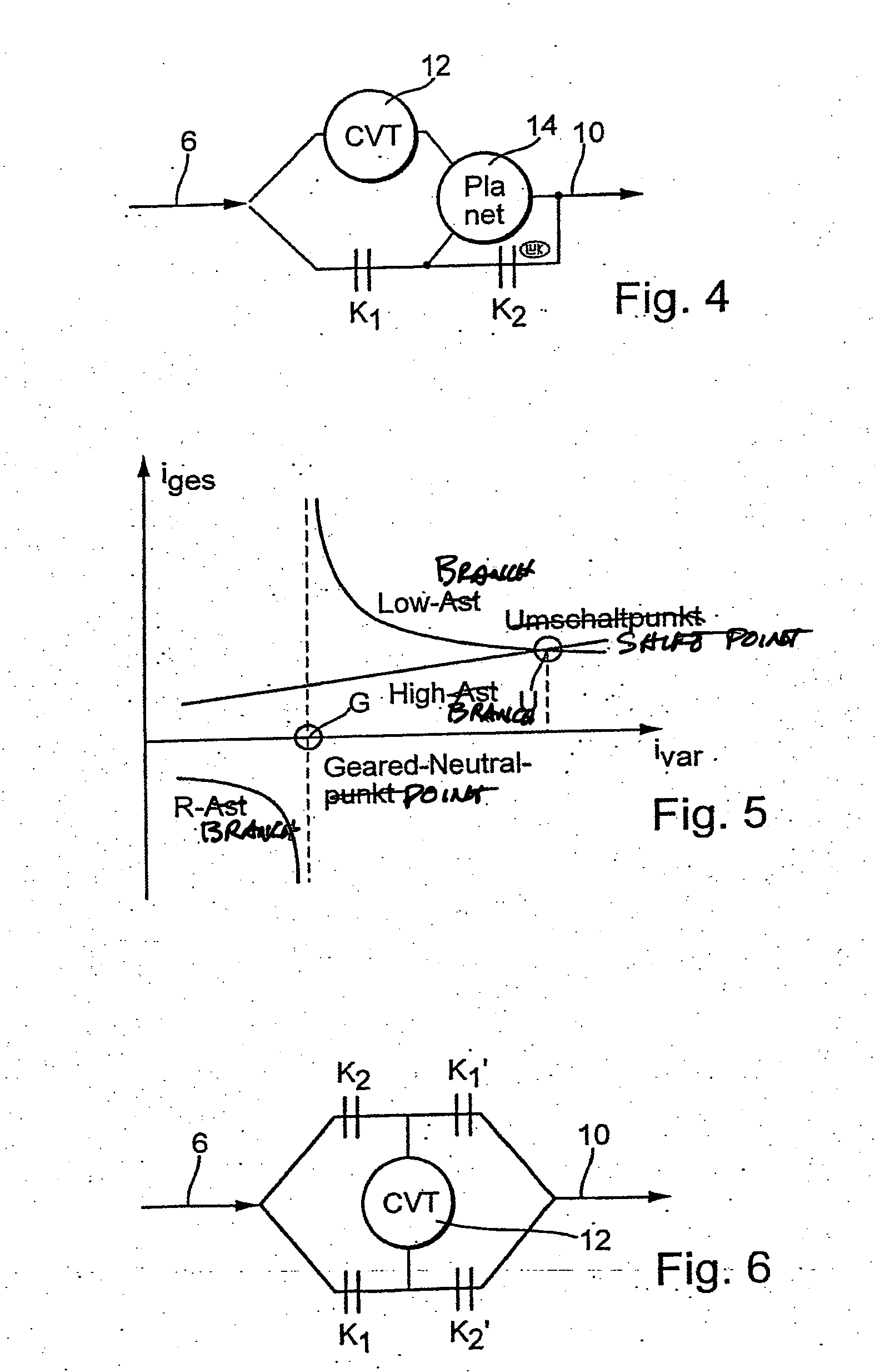
[0023] Briefly stated, in accordance with one aspect of the present invention, a method for regulating the transmission ratio of a power-branched automatic transmission is provided. The transmission includes an input shaft driven by a engine, a variator with a continuously variable transmission ratio, a gear transmission, an output shaft, and at least two control clutches. The variator and the gear transmissions are connected with one another through the control clutches in such a way that when traversing the overall transmission ratio range of the power-branched transmission, within a first ratio range the adjustment range of the variator is traversed in one direction, and within a second transmission ratio range in the opposite direction. At least one regulator parameter of an adjustment regulator utilized to set the transmission ratio of the variator changes its sign during the transition between the transmission ratio ranges.
[0023] Briefly stated, in accordance with one aspect of the present invention, a method for regulating the transmission ratio of a power-branched automatic transmission is provided. The transmission includes an input shaft driven by a engine, a variator with a continuously variable transmission ratio, a gear transmission, an output shaft, and at least two control clutches. The variator and the gear transmissions are connected with one another through the control clutches in such a way that when traversing the overall transmission ratio range of the power-branched transmission, within a first ratio range the adjustment range of the variator is traversed in one direction, and within a second transmission ratio range in the opposite direction. At least one regulator parameter of an adjustment regulator utilized to set the transmission ratio of the variator changes its sign during the transition between the transmission ratio ranges.
[0074] In accordance with a further solution to the above-mentioned problem, an anticipatory control of the different contact pressures of the disk pairs of the variator, which are respectively a function of the transmitted torque, is not shifted during the transition between shift ranges. That anticipatory control, which is a function of the current torque on the variator, is nonetheless adapted to the new range.
[0023] Briefly stated, in accordance with one aspect of the present invention, a method for regulating the transmission ratio of a power-branched automatic transmission is provided. The transmission includes an input shaft driven by a engine, a variator with a continuously variable transmission ratio, a gear transmission, an output shaft, and at least two control clutches. The variator and the gear transmissions are connected with one another through the control clutches in such a way that when traversing the overall transmission ratio range of the power-branched transmission, within a first ratio range the adjustment range of the variator is traversed in one direction, and within a second transmission ratio range in the opposite direction. At least one regulator parameter of an adjustment regulator utilized to set the transmission ratio of the variator changes its sign during the transition between the transmission ratio ranges.
[0022] The invention is applicable for all types of power-branched transmissions with a variator, especially a belt-driven conical-pulley transmission. The invention is especially applicable for use in power-branched transmissions installed in motor vehicles.

Problems solved by technology

Various problems arise from the combination of several individual actuations (clutches and / or brakes, adjustment regulators) that act upon the same power train.
The following can be identified as problems for the present power-branched automatic transmission with a variator: power train oscillations that arise during shifting, or excessive wear of the frictionally-engaged elements in the variator or the endless torque-transmitting means.

Method used


Image

  • Methods for regulating the gear ratio of an automatic power-branched transmission, and automatic power-branched transmission
  • Methods for regulating the gear ratio of an automatic power-branched transmission, and automatic power-branched transmission
  • Methods for regulating the gear ratio of an automatic power-branched transmission, and automatic power-branched transmission

Examples


example

[0163] A shift into the unbranched region (low branch) is only allowed when the target overall transmission ratio iges target is larger by at least one Δ value than the transmission ratio at which the range shift U takes place with rotational speed equality.

[0164] When a range change takes place because the target transmission ratio is greater than the hysteresis region, the target transmission ratio should be approached in a suitable manner, for example, through linear reduction of the transmission ratio difference Δiges.

[0165] An alternative or additional solution to the problem can lie in that a range change takes place only after expiration of a predetermined time period since the last range change.

[0166] A still further or additional solution can lie in that a downshift into the old operating range only occurs when the driver expresses the wish for it through an appropriate signal, for example operates the accelerator pedal since the last range change, operates the service b...


PUM


Abstract

A method for regulating or controlling the transmission ratio of an automatic power-branched transmission. Power is transmitted through a shaft driven by an engine, a variable speed drive, a gear transmission, a driven shaft, and at least two control clutches. The variable speed drive and the gear transmission are connected to each other in such a way that the regulating range of the variable speed drive is traversed in one direction within a first range of transmission ratios, and is traversed in the opposite direction within a second range of transmission ratios during traversing of the entire range of transmission ratios. The shifting strategies result in reduced wear of the endless belt device and allow for comfortable changing between the transmission ratio ranges.

Description

BACKGROUND OF THE INVENTION [0001] 1. Field of the Invention [0002] The invention concerns a method for regulating the transmission ratio of a power-branched automatic transmission. The invention furthermore concerns a power-branched automatic transmission for carrying out the method of the invention. [0003] 2. Description of the Related Art [0004] Transmissions with a continuously variable transmission ratio (CVT transmissions) are being increasingly installed in passenger cars because of their higher comfort and the reduced fuel consumption that is possible relative to automatic transmissions operating in steps and exclusively with planetary gear sets. Power transfer takes place in CVT transmissions for example through an endless torque-transmitting means that circulates between two pairs of conical disks, whereby the effective radius of each conical disk pair is variable by changing the spacing between the disks. Other steplessly adjustable transmissions are based upon rolling el...

Claims


Application Information

Patent Timeline
Patent Type & Authority Applications(United States)
IPC IPC(8): F16H37/08F16H37/02F16H61/00F16H61/662F16H61/664
CPCF16H37/084F16H37/0846F16H61/66254F16H61/66272F16H2037/025Y10T477/675F16H2061/6614F16H2061/6616Y10T477/619Y10T477/679Y10T477/33F16H2037/088F16H37/08
Inventor BITZER, FRANZLAUINGER, CHRISTIANREUSCHEL, MICHAELVORNEHM, MARTINTEUBERT, ANDREHOMM, MANFREDMULLER, ERICSTEHR, REINHARDWALTER, BERNHARD
Owner LUK LAMELLEN & KUPPLUNGSBAU BETEILIGUNGS KG
Learn More