Tool drive system

a technology of drive system and tool, which is applied in the direction of driving apparatus, drilling machines and methods, construction, etc., can solve the problems of reduced leverage or limited workspace, difficult user positions, and reduced leverag

Inactive Publication Date: 2005-08-02
ULLAH RIZWAN
View PDF2 Cites 1094 Cited by
  • Summary
  • Abstract
  • Description
  • Claims
  • Application Information

AI Technical Summary

Benefits of technology

[0005]It is a further object and feature of the present invention to provide such a tool drive system that provides an increase in the leverage of the user.
[0006]It is a further object and feature of the present invention to assist in providing a speed differential between the input and output of each respective drive element.
[0021]Further, it provides such a system wherein: such at least one housing comprises a circular periphery; such circular periphery comprises a set of evenly-spaced teeth; at least one of such at least one rotatable first shaft and at least one rotatable second shaft comprises at least one shaft housing element comprising at least one shaft housing tooth structured and arranged to fit between a pair of such evenly-spaced teeth; and such at least one shaft housing tooth is removably engagable with such evenly-spaced teeth, wherein the user may set such at least one angle.
[0028]It also provides such a system wherein such at least one bar connects such housing with such at least one rotatable first shaft and such at least one rotatable second shaft. And, it provides such a system wherein: such at least one housing comprises a circular periphery; such circular periphery comprises a set of evenly-spaced teeth; at least one of such at least one rotatable first shaft and at least one rotatable second shaft comprises at least one shaft housing element comprising at least one shaft housing tooth structured and arranged to fit between a pair of such evenly-spaced teeth; and such at least one shaft housing tooth is removably engagable with such evenly-spaced teeth, wherein the user may set such at least one angle.

Problems solved by technology

Removal with a tool driver that has a fixed position can result in difficult user positions and decreased leverage or limited workspace.

Method used


Image

  • Tool drive system
  • Tool drive system
  • Tool drive system

Examples


Embodiment Construction

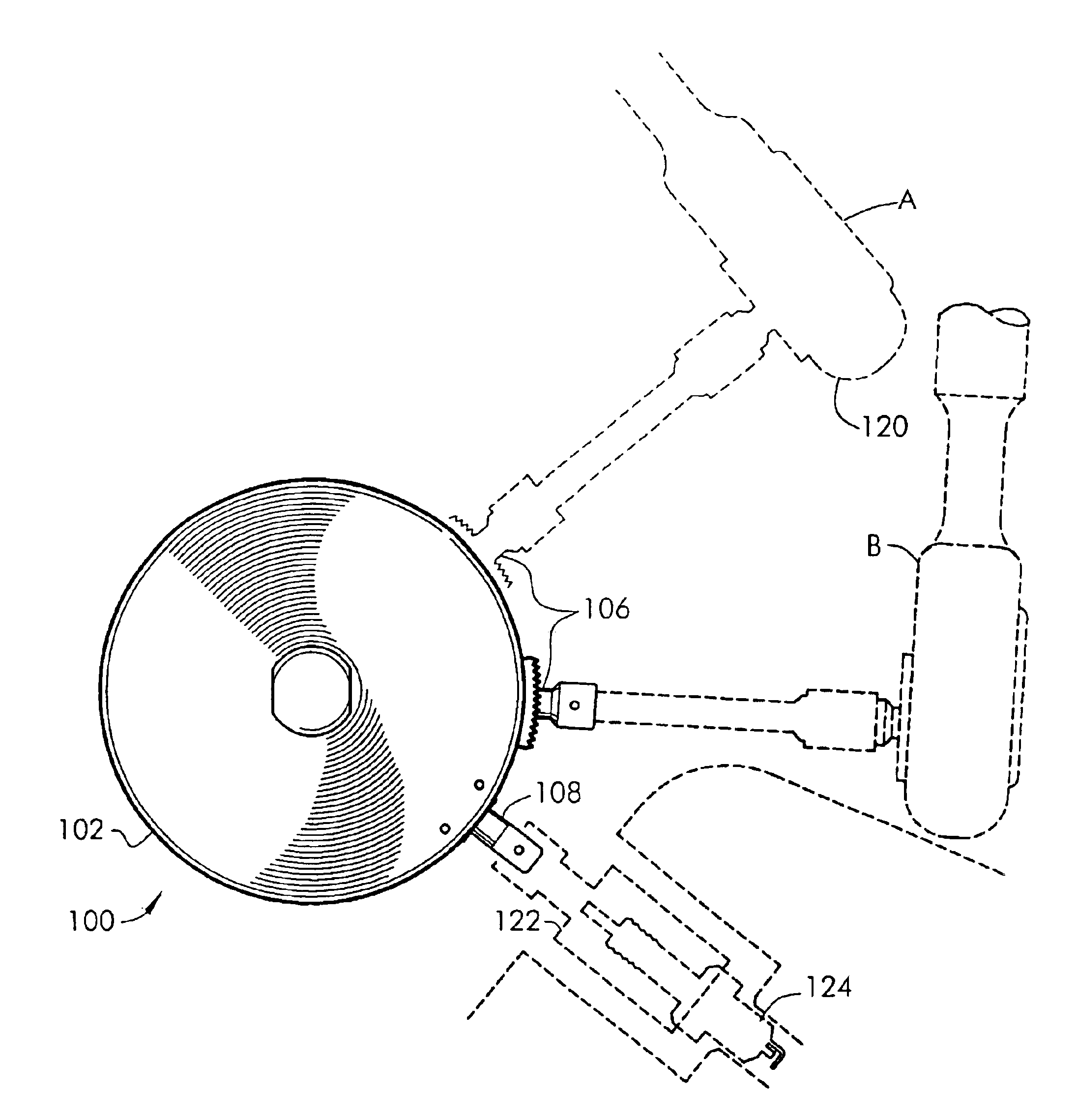
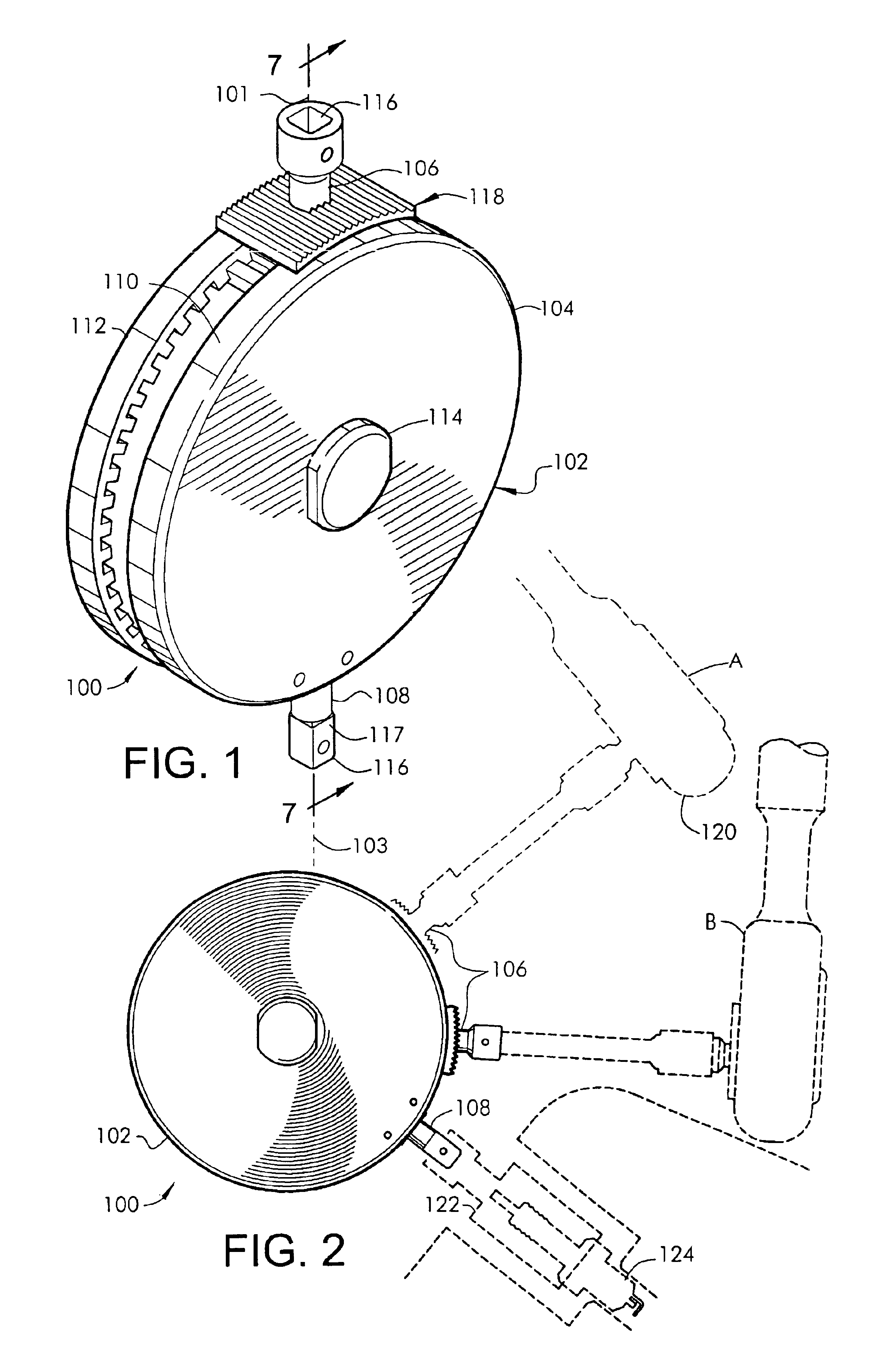
[0043]Reference is now made to the drawings. FIG. 1 is a perspective view of the tool drive system 100 according to a preferred embodiment of the present invention. Preferably, the tool drive system 100 comprises a power transfer assembly 102, as shown. Preferably, the power transfer assembly 102 comprises a housing 104, an input shaft 106, having an axis of rotation 101 and an output shaft 108 having an axis of rotation 103, as shown (embodying herein movement transfer means for rotating such at least one rotatable second shaft when such at least one rotatable first shaft is rotated). Preferably, the housing 104 is split into two halves, half 110 and half 112. Preferably, each respective half 110 and half 112 are connected, preferably by a connector 114 (embodying herein wherein such movement transfer means further comprises connector means for connecting such at least one rotatable first shaft and such at least one rotatable second shaft; and embodying herein at least one movement...


PUM


Abstract

A tool drive system for transferring rotational power from a rotational tool, such as a drill or ratchet, to at least one input drive shaft which then transfers the power to at least one output drive shaft. The angle of at least one input drive shaft being adjustable relative to at least one output shaft. The tool drive system comprises a round housing with an angle adjuster attached to the input shaft that assists in adjusting and locking the angle of the input shaft relative to the output shaft in an almost circular span. The input and output shafts may be positioned in a user-selected gear ratio from the input to output shafts or vice versa.

Description

CROSS-REFERENCE TO RELATED APPLICATION[0001]The present application is related to prior provisional application Serial No. 60 / 422,024, filed Oct. 29, 2002, entitled “TOOL DRIVE SYSTEM”, from which priority is claimed, the contents of which are incorporated herein by this reference and are not admitted to be prior art with respect to the present invention by the mention in this cross-reference section.BACKGROUND[0002]This invention relates to providing a tool drive system for transferring rotational power from at least one first driver to at least one second driver. More specifically, it relates to a tool drive system providing at least one input and, at least one output, drive shaft in which the angle of at least one drive shaft is adjustable.[0003]Typically, a user may utilize a tool drive system such as, for example, a ratchet tool, to turn a tool attachment sized to remove a fastener such as a bolt or screw. Typically, such fasteners are located in a variety of angular positions ...

Claims


Application Information

Patent Timeline
Patent Type & Authority Patents(United States)
IPC IPC(8): B23Q5/00B23Q5/04
CPCB23Q5/043B23Q5/045
Inventor ULLAH, RIZWAN
Owner ULLAH RIZWAN
Why Eureka
Try Eureka